Margay WN-5040-720 User Guide
WN-5040-720 Margay 50" Display Wall Unit User Guide 070-0148-04 26 April 2005 i
©2005 by Clarity Visual Systems™, Inc. All Rights Reserved. Contents of this publication may not be reproduced in any form without permission of Clarity Visual Systems, Inc. Trademark Credits Windows™ is a trademark of Microsoft Corp. Clarity's Big Picture™ is a trademark of Clarity Visual Systems, Inc. DLP™ and DMD™ are trademarks of Texas Instruments, Inc. All other names are trademarks or registered trademarks of their respective companies.
LIMITED WARRANTY. Clarity warrants to Buyer that the WN-5040-720 (the “Product”), if properly used and serviced, will perform substantially in accordance with the product data sheet and users manual, and will be free from defects in material and workmanship for one year following date of shipment. This warranty does not apply to air filters and other consumable parts.
iv
Feedback About Manuals Clarity Visual Systems, Inc., is constantly striving to provide the best product available at a reasonable cost. Part of this Clarity product is the manual. If you have found an error in this manual, or if you would like to make any comments about it, you may use this form. This form is used with the MARGAY USER GUIDE, PART NUMBER 070-0148-04 DATED 26 APRIL 2005 You may fax this form to Clarity Visual Systems, Attention: Manuals at +1 503 570 4657.
Contents 1 Basic Information About Margay … 1 1.1 Accessories For Margay … 2 1.2 Your Safety and Margay’s Safety … 4 2 Installing … 7 2.1 2.2 2.3 2.4 What You Will Do … 8 Installing the VIM (Video Input Module) … 10 Installing the Big Picture Key … 12 Building the Wall, First Row … 14 2.4.1 Building the Wall, Second Row and Up … 16 2.4.2 Building a Banner, Upside Down … 18 2.5 Connections … 20 2.5.1 Connections, Analog & Digital Sources … 22 2.5.2 Connections, Video Sources … 24 2.5.
3.2.3 Adjusting to Video Sources … 50 3.3 Color Balancing a Wall of Margays … 52 3.4 Spreading One Picture Over a Wall … 54 3.4.1 Scaling and Cropping … 56 3.4.2 Zoom and Position … 58 3.4.3 Viewport Adjustment … 60 3.5 Saving Your Work & Recalling a Memory … 62 3.5.1 Memory: What Is Saved? And Where? … 64 4 Operating … 67 4.1 4.2 4.3 4.4 4.
1 Basic Information About Margay 1.1 Accessories For Margay … 2 1.
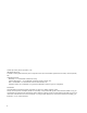
1.1 Accessories For Margay Check what you received with the Margays The number in (parentheses) is the quantity you should have for each Margay. 1. Screen Support (1 for each Margay on the bottom row; shipped per order, not per display) 2. Front screws, (2) 3. Long side-to-side bolts (1), washers (4), and wing nut (1) 4. Short side-to-side bolts (1), washers (4), and wing nut (1) 5. Vertical screws, ¼"-20 bolts (2) 6. Suction Cup (1) 7. VGA cable (1) 8. DVI cable (1) 9. AC power cord (1) 10.
2. Front screw 3. Long side-to-side bolt 1. Screen Support (may vary in design) One of these for each Margay on the bottom row. 5. Vertical screw ¼–20 bolt 4. Short side-to-side bolt 8. DVI cable 6. Suction Cup 9. Power cord 7. VGA cable 10.
1.2 Your Safety and Margay’s Safety The fully assembled display weighs about 68 lbs (30.8 kg). When assembling a wall, you will need two people to handle the Margay. WARNING The lamp needs very high voltages to start, around 15,000 volts. WARNING The lamp gets very hot. Allow it to cool before removing it. WARNING The lamp produces lots of light and UV radiation (ultra-violet) as well. UV light can damage your retinas.
5
6
2 Installing 2.1 What You Will Do … 8 2.2 Installing the VIM (Video Input Module) … 10 2.3 Installing the Big Picture Key … 12 2.4 Building the Wall, First Row … 14 2.4.1 Building the Wall, Second Row and Up … 16 2.4.2 Building a Banner, Upside Down … 18 2.5 Connections … 20 2.5.1 Connections, Analog & Digital Sources … 22 2.5.2 Connections, Video Sources … 24 2.5.3 Connections, Power … 26 2.5.4 Connections, Control: RS232 & RS485 … 28 2.6 Installing and Removing Screens … 30 2.6.
2.1 What You Will Do The series of steps here give only a basic outline of the installation process. See the specific sections for details (page numbers in parentheses). Installation 1. Unpack the Margays. Leave the screens in their containers. You won’t need the screens for a while. 2. If it was purchased, install the VIM (Video Input Module) in each Margay. (10) 3. If it was purchased, install the Big Picture key in each Margay. (12) 4. Build the wall of Margays, leaving the screens off. (14) 5.
9
2.2 Installing the VIM (Video Input Module) It is easier to install the VIM board in Margays before they get stacked in a wall. The Video Input Module option is installed in the field. You will install the VIM (Video Input Module) in the Margay’s electronics module. (The electronics module is the part the receives all the input and output cables.) If the electronics module is installed in the Margay, you will remove it partially. 4. Pull the module up and partly out. a.
6. Put in the four screws. Be sure the VIM is pressed well into the socket. One of 4 screws. 7. Put the electronics module back in place and secure it with the two screws. 8. Reconnect power, if you removed it earlier.
2.3 Installing the Big Picture Key Clarity’s Big Picture™ key allows a wall of Margays to spread one picture over the entire wall. The Big Picture key is installed in the field. You can install the Big Picture key without removing the electronics module. 3. Plug the BP key into its socket. 1. Open the door to the electronics module. CAUTION Be sure all six pins go in the socket holes. If the key is installed incorrectly, the entire electronics module may not function at all. 2.
13
2.4 Building the Wall, First Row It is most important to make the first row straight. Do not put the screens on yet. Laying the first row 1. Set the first row of Margays side by side without the screens. Bolt them loosely together near the bottom with the long side-to-side bolts, washers and wingnuts. 2. Attach the screen supports to the front edge of the first row. The screen support only mounts one way and is used on the bottom row only. It provides a stop or rest for the bottom screens. 3.
Using string to see that the row is straight First row with screen supports in place Screen support bolt, two at each end Side-to-side bolt with wing nut at bottom of neighbor Margays 15
2.4 Building the Wall, First Row 2.4.1 Building the Wall, Second Row and Up If the first row is straight and solid, the rest of the rows will be easier. Continuing to build the wall 1. Stack another row of Margays on the first row. As you stack, be careful with the pins that align the rows. 3. Then bolt the Margays top-to-bottom through the top-to-bottom hole using the Vertical bolts, ¼"-20. 2. As each Margay is placed in the second row, secure it to the lower unit with two Front screws. 16 4.
end of the row has shorter side-to-side bolts to secure just two Margays together. CAUTION For high walls, over 2 units high, and for all tilted walls, see the safety instruction below. Safety with high or tilted walls Because the Margay is so narrow front to back, there is a danger of tipping with high walls. Margay has tie-back points on the rear to prevent this. Use these tie-backs to secure the Margay wall to a structural part of the building. Don’t wait until the wall is finished.
2.4 Building the Wall, First Row 2.4.2 Building a Banner, Upside Down It is possible to hang a single row of Margays upside down to make a banner. Be sure the ceiling can hold them. Clarity does not provide any special brackets to hang a Margay upside down. There are too many variables to consider, so the method to use is best determined on site. Whatever you use to attach Margays overhead, it must be capable of sustaining five (5) times the weight of a Margay, which is 68 lbs or 30.8 kg.
. 19
2.5 Connections Margay has four groups of connectors. All inputs are paired with loop-thru outputs (except RS232 In). The inputs are toward the rear of the Margay. Analog and digital connectors Two analog connectors and one digital (DVI) connector have their separate loop-thru outputs. The Analog outputs (buffered) always carry the corresponding analog input picture. The digital output is different. The digital output carries a digitized version of the selected input.
Electronics module as seen from the front. The electronics module door is open.
2.5 Connections 2.5.1 Connections, Analog & Digital Sources The Digital Out connector carries the selected input. All of the source inputs, the picture inputs, have loop-thru output connectors. These loop-thrus are buffered. • Analog 1 and Analog 2 are 15-pin VGA-type connectors. Margay will accept a wide range of computer resolutions up to 1600 × 1200 and 1920 × 1080. Each of these connectors has a dedicated loop-thru output.
In Out 23
2.5 Connections 2.5.2 Connections, Video Sources Video is a option installed in the field. If you did not install the optional Video Input Module (VIM), skip this section. (2.2 “Installing the VIM (Video Input Module)” on page 10) Composite video Connect an NTSC, PAL, or SECAM composite source to COMPOSITE IN. Loop-thru from COMPOSITE OUT. S-video Connect an NTSC or PAL S-video source to the 4-pin DIN connector, S-VIDEO IN.
25
2.5 Connections 2.5.3 Connections, Power AC loop-thru means you won’t need as many mains sockets. Bring in AC power next to the electronics module. The voltage can be 115 (90V – 132V) or 230 (200V – 254V). Loop the AC power out to the next Margay, if you wish, but limit this to four (4) connected Margays for 115V operation and eight (8) connected Margays for 230V operation. WARNING Do not exceed the recommended number of Margays linked in series for AC power or the current draw will be too great.
AC power in and out No more than 4 2 3 6 1 4 5 115 VAC 27
2.5 Connections 2.5.4 Connections, Control: RS232 & RS485 With serial control, you can control a whole wall, several walls, and any single display in them. Connect to the computer Connect the first cube in the wall to the serial out port of a computer or another type of controller, such as a video controller. Connect with computer serial cable, such as Cat-5, using straight-thru cable.
29
2.6 Installing and Removing Screens The Margay screens in a wall are quite close together, so the order in which you remove them from a wall is very important. WARNING Do not install or remove any screen until you have read and understand this section. If screens are installed or removed improperly, they may be damaged. About “no-mullion” screens One of the best features of Margay is its “zero mullion” screens.
View from above a row of Margays When Margays are installed in a row, the screens are very close together. Pulling a screen from the outside of the row causes it to bind with its neighbor. Top of Margay 1 Top of Margay 2 Top of Margay 3 Screen 1 Screen 2 Screen 3 Top of Margay 1 Top of Margay 2 Top of Margay 3 Screen 1 Screen 2 Screen 3 Pulling a screen from the outside edge. ouch DON'T DO THIS! The proper way is to make the first pull on the neighboring edge of an outside row.
2.6 Installing and Removing Screens 2.6.1 Installing the Screens Start in the middle of the bottom row and work outward and upward. First 1. Be sure the wall of Margays is straight and the corners are square. Measure the diagonals of the whole wall. If the diagonals are equal, the wall is a perfect rectangle. 2. The screen supports should be installed on the bottom row of Margays. Screen supports Then 3. Start in the middle of the bottom row and install that screen. a.
8 5 5 8 7 4 4 7 6 3 3 6 2 1 1 2 In a wall of Margays, install the screens starting with the center of the bottom row and work out to the ends. Then install the screens above the middle until you have an inverted T. Finally, install the rest of the rows, complete each row before moving up.
2.6 Installing and Removing Screens 2.6.2 Opening or Removing a Screen You will hear the screen latch click and release. Pulling up a little keeps this screen from rubbing the screen below. Release the latch at top and bottom of one side. Removing a screen from a single Margay standing alone is not a problem. Simply grasp the sides of the screen and pull forward sharply. The spring latches will pop loose.
7. 4 Then this edge. 3 8. 2 Now here. 1 9. 4 Then this edge. 3 10. 4 3 2 Finally, pull this edge. 1 This may seem like a long way to pull a single screen, but this order of operations helps prevent screen damage.
2.6 Installing and Removing Screens 2.6.3 Opening a Screen Temporarily for Work The Margay screen props open for work from the front. 1. Carefully open the screen of the Margay you want to work on. See 2.6.2 “Opening or Removing a Screen” on page 34. 2. Pull the screen all the way out. 3. Use the hook to hold the screen at an angle. 4. Be sure to close the hook along the slider before closing the screen.
3 Aligning and Adjusting 3.1 Adjusting Margay’s Engine: Important Step … 38 3.2 Adjusting Each Margay To Its Source … 42 3.2.1 Adjusting to Computers, Analog RGB … 44 3.2.1.1 Adjusting Input Levels Manually … 46 3.2.2 Adjusting to Computer Sources, Digital … 48 3.2.3 Adjusting to Video Sources … 50 3.3 Color Balancing a Wall of Margays … 52 3.4 Spreading One Picture Over a Wall … 54 3.4.1 Scaling and Cropping … 56 3.4.2 Zoom and Position … 58 3.4.3 Viewport Adjustment … 60 3.
3.1 Adjusting Margay’s Engine: Important Step The optical engine must be adjusted to aim the picture accurately at the screen. Although the optical engine was perfectly adjusted when the Margay left the factory, vibration along the way may have moved it. CAUTION It is important to check this mechanical adjustment of the optical engine before any electronic adjustments are made to the picture. Aligning the optical engine 1. Open the Engine Alignment menu. 2. In the last item in the menu, choose Grid.
4. Loosen the two mounting nuts on the left side of the carriage. 8. To move the screen image up or down tighten or loosen the adjustment screws on the both sides of carriage. Loosen these two nuts Move image up or down by adjusting this screw... 5. Loosen the single mounting nut on the right side of the carriage ... and this screw Loosen this nut 6. To move the screen image to the right, move the carriage to its left (as you face the carriage from the back of the unit). 7.
40
Alignment Dashes Use the Alignment Dashes pattern to show how many pixels are visible at each edge. Use the Grid pattern to adjust rotation and to align all patterns in a wall.
3.2 Adjusting Each Margay To Its Source 3.2 Adjusting Each Margay To Its Source The source picture—from computer, video, DVD—is not always perfect in its size or strength; it does not always conform exactly to a standard. Margay has a way to compensate for this. Computer sources vary quite a bit from computer to computer. They even vary between video outputs on the same video card. Video sources vary more. To make the Margay respond correctly to these non-standard sources we adjust Input Levels.
43
3.2 Adjusting Each Margay To Its Source 3.2.1 Adjusting to Computers, Analog RGB 3.2.1 Adjusting to Computers, Analog RGB The best way to adjust levels is the semi-automatic method. Adjusting levels semi-automatically This is quick and easy if you can get a black picture and a white picture from the source computer. 1. Display a black picture from the source. This must come from the computer source that will be used for the program.
45
3.2 Adjusting Each Margay To Its Source 3.2.1.1 Adjusting Input Levels Manually It is rarely necessary to adjust input levels manually. You can skip this section. Adjusting levels manually 1. Display an all-black picture from the source computer. 2. Press LEVEL on the remote. 3. Select MANUAL BLACK LEVEL and adjust it up and down with the +/– keys to make the three CENTER POINT values go to zero.
47
3.2 Adjusting Each Margay To Its Source 3.2.2 Adjusting to Computer Sources, Digital Digital sources do not normally need adjustment, but the controls are there if you need them. These controls are advance level controls and should not be adjusted unless you have been briefed by the factory or are familiar with black level adjustments. They are used to correct the digital blacks that come from video cards that have incorrect levels.
This form of the Input Levels menu appears when the current source is Digital and the colorspace is RGB. This form of the Input Levels menu appears when the current source is Digital and the colorspace is YPbPr.
3.2.3 Adjusting to Video Sources Video adjustments are quite a bit like the controls on a television receiver. Adjusting the picture 1. Select a video source in the Picture menu. When the VIM option is installed (Video Input Module) Margay has available a. one composite video, b. one S-Video, and c. one component (YPbPr) input. 2. Press LEVEL on the remote. 6. If the color bar pattern has a pluge, you can use it to adjust Brightness.
Saturation Match these Match these Adjust Saturation so the outside bars match when Blue Only is checked. Hue Match these Match these Adjust Hue so the inside bars match when Blue Only is checked.
3.3 Color Balancing a Wall of Margays Color Balancing can be done before or after Input Levels. The object of color balancing is to make the individual units show the same colors. When we see a red car move across a video wall from one display to another, we want it to have the same color for the whole trip, not change from red to maroon to orange. The displays naturally have slightly different colors from one display to the next, because of slight variations in the lamp and DLP™ engine.
Color Balance values are saved for all input sources in the same memory location. Color Balance is the same for all sources. Bright Output brightness Changes in the White value moves this end point. 100 31 Changes in the White values affect the Gray values. 0 Dark Black Output brightness 10. Pick a display next to the baseline display, above, below, or to the side. This will be the variable display. Turn on the Color Balance menu for this variable display by pressing ENTER.
3.4 Spreading One Picture Over a Wall 3.4 Spreading One Picture Over a Wall Whether you use Clarity’s Big Picture™ or an external video processor, your goal is to make the picture fit together properly at the edges. When this is done correctly, the viewer does not notice the black lines separating the screens. If you have not checked the optical engine alignment on each Margay, do so now. (See 3.1 “Adjusting Margay’s Engine: Important Step” on page 38.
55
3.4 Spreading One Picture Over a Wall 3.4.1 Scaling and Cropping Sometimes the picture does not fit the wall. If the source picture is video from a DVD, the aspect ratio is probably 1.77 (16x9), the same as HDTV. The aspect ratio of a picture is its width divided by its height. 1024 ÷ 768 = 1.33 The aspect ratio of a Margay is 1.77 (16x9), the same as HDTV. When the source picture’s aspect ratio is not the same as the Margay wall, you have to do something to make the picture fit.
the top is cropped off. This would happen when the Justify is BOTTOM. • Widescreen means force the aspect ratio to 16 x 9 (1.77), the standard for many DVD movies. • Normal forces a 4 x 3 (1.33) aspect ratio, the ratio of standard television. No Big Picture key If there is no Big Picture key, the whole picture will appear on the screen, and the menu looks like this: You can’t spread one picture over several Margays, but you can make the picture fit one Margay is the ways described above.
3.4 Spreading One Picture Over a Wall 3.4.2 Zoom and Position Position moves the picture on the screen. This is NOT the same as optical engine alignment. Zoom adjusts the edges of the picture to make it fit with the other pictures in a wall. Position Press the MISC button once to open the Picture Position menu. The four arrow keys move the picture on the screen. The numbers for Horizontal and Vertical Position refer to the number of pixels from sync to the first displayed pixel.
59
3.4.3 Viewport Adjustment The Viewport menus adjust the image on the DMD™. What is the DMD? DMD stands for Digital Micromirror Device. It is Texas Instrument’s name for their patented chip that produces the pictures in a DLP™ (Digital Light Processing) system. The DMD chip is about the size of a postal stamp and contains, in the case of Margay, 1280 by 720 pixels. What is Viewport? The Viewport menu adjust the number of pixels actually used on the DMD.
61
3.5 Saving Your Work & Recalling a Memory 3.5 Saving Your Work & Recalling a Memory Some saving is done automatically, but there are big advantages to saving your work manually. There is more information about memories starting on page 78. How automatic save works Whatever changes you make with the remote control or RS232 commands, these changes are saved automatically. If you change sources (switch to another input connector) and come back to this source, everything you did before will be “recalled.
ENTER ENTER 63
3.5.1 Memory: What Is Saved? And Where? Margay’s automatic memories work well, but the best way to save and recall is with the numbered memory slots, because they recall everything. In the Margay some parameters (values) are associated with the mode. The mode is primarily the horizontal and vertical resolution and the vertical frequency of the incoming source picture. It is more than this, but if you think of it this way, you will be close enough. Some parameters are associated with the input.
computer connected to Analog 1. Then later, using the same input connector but a different computer you set up the Margay for a 1600x1200 @ 60Hz. You re-adjust the Black and White Levels, because they are different. Still later you plug in the first computer with its 1024x768 @ 65Hz picture. Immediately, the Margay recognizes that it has seen this signal type before, and it recalls the Black and White Levels from its internal memory.
66
4 Operating 4.1 Selecting a Source … 68 4.2 Normal Start Up … 70 4.3 Controlling Margay with Remote … 72 4.4 Controlling Margay with RS232/RS485 … 74 4.
4.1 Selecting a Source The “source” is the picture coming into the Margay. It may be from a computer, a video, or a DVD player. Selecting the source 1. Press MENU on the remote. 2. Select PICTURE and press ENTER. 3. Select SOURCE and press the lEFT ARROW key. 4. Choose the source you want and press ENTER. 5. Press MENU again to close all menus. Selecting a source means choosing an input connector so you can see the picture coming into that input.
69
4.2 Normal Start Up It is often helpful to know what the sequence of events is when the Margay starts. Start up sequence When AC power is turned on, it seems that nothing happens for a few seconds. The electronics module is starting up and initializing itself. Next, if the optical engine is warm, the fans start. During this time, you cannot turn the lamp on. It shortens lamp life to turn it on when it is hot, so the fans run for a minute or so to be sure it is cool.
71
4.3 Controlling Margay with Remote You can control Margay with the remote control or with RS232 commands. Remote control The remote control projects a series of IR (infrared) pulses to the Margay for control. Aim the remote control at the screen and press MENU. The main menu should be visible, if the lamp is on. • Something is blocking the IR receiver in the Margay. • IR remote action was disabled by an RS232 command. The remote control has a large spread of its IR radiation.
73
4.4 Controlling Margay with RS232/RS485 Connect the RS232 In to the computer. Loop thru with RS485. Remote control with serial commands is a good way to control a wall while it is operating. It’s also an easy way to control Margays in a wall during initial setup using one of the Clarity utility programs. • To address all the cubes with a certain Unit ID, use an address like *0 or *3. Open Clarity’s website in your internet browser. www.ClarityVisual.com In the top banner, click on LOGIN.
75
4.5 Asset Tag and Display Status The Asset Tag feature allows you to identify each Margay by its serial number or in other ways. To see the current Asset Tag, press MONITOR. • Interlock—If the interlock is Open, the lamp will not light (unless the interlocks have been bypassed to service the display).
5 Troubleshooting 5.1 Troubleshooting Tips … 78 5.2 Reading the On Screen Code … 80 5.
5.1 Troubleshooting Tips Margay has several troubleshooting aids. On Screen codes The On Screen code is a series of red and amber lights that can flash on the screen to tell you what is wrong. These flashing lights are particularly helpful when the lamp won’t light. See 5.2 “Reading the On Screen Code” on page 80. Inside LEDs The LEDs on the electronics module give you information about the state of the Margay. See 5.3 “Reading the LEDs” on page 82.
display. However, there is a very tiny chance that the part in the box doesn’t work. If you test a part by putting in a known good part, you get better information.
5.2 Reading the On Screen Code Red and amber lights flashing on the screen can tell you what is wrong. Turning on the On Screen code With the remote control, press MONITOR. You should see the red or amber lights flashing on the screen. This also opens the Display Status menu, but of course, you won’t see it if the lamp is off. If there is a bright picture, it may be difficult to see these lights. They are soft, out of focus lights. Move around to see them.
Margay On-Screen Codes Starts with Amber. Priority Each block represents 0.
5.3 Reading the LEDs The LEDs on the electronics module can give you more detailed information about the Margay’s state. To see LEDs The LEDs are on the electronics module. From the rear, you can see them easily, that is, if there aren’t too many cables in the way. LEDs From the front, open the screen. Then open the electronics module door to the right.
LEDs in Margay When the LED is… LED Name Off Green Amber Red Ready Lamp is on (or no power) Source Source absent Valid source present Lamp Lamp off Lamp on Lamp striking Lamp failed Fan Fan off Fan is running Fan failed recently, but is now running Fan failed Lamp disabled Remote IR Not receiving IR now Receiving IR radiation No power to electronics Door closed & rear panel closed Lamp enabled Either door was open, now closed Must cycle AC power to reset and enable lamp Either doo
84
6 Maintenance for Margay 6.1 Changing a Lamp … 86 6.2 Changing the Air Filter … 88 6.
6.1 Changing a Lamp You can change the lamp from the front or the rear. When should I change the lamp? Change the lamp when it fails. Lamp life is the median life of a large sample of lamps. Median means middle. It is not what most people think of as average. Suppose the specification for lamp life is 5000 hours. If you had a large group of these lamps, more than 100, and you turned them all on at the same time, after 5000 hours at least half of them would still be on.
6. Loosen the lamp screw to the right rear of the lamp. 3. Loosen the lamp screw. 4. Pull the lamp toward you and to the right. 5. Disconnect the lamp cable. Replacing the lamp 1. First, plug in the lamp cable. Be sure it is fully seated. WARNING If the lamp cable is not fully seated on the lamp plug, the lamp will not operate properly. Overheating may occur. 7. When the screw is loose, move the lamp to the rear about 3/8" (10 mm), then to the left, and lift it out, still connected. 8.
6.2 Changing the Air Filter Clean, cool air is essential for proper Margay operation. When should I change the air filter? When it gets dirty, change it. Unfortunately, there is no absolute rule about when to change an air filter. For some installations the environment has clean, dust-free air, such as a corporate lobby. The air filter may be good for a year or more. In other environments—airports, subway terminals—the air full of dust and dirt all the time.
Removing the air filter from the rear 1. Turn off the AC power switch and remove the power cord 2. Remove the rear panel (6 ¼-turn screws). 3. Push open the electronics module door. 4. Reach around through this door and loosen the light shield screw. 5. Push the light shield up until it latches out of the way. 6. Lift the air filter up and forward, away from you.
6.3 Cleaning the Screen and Mirrors Dirt is everywhere, and unless the displays you service are in a super-clean room, from time to time you will have to clean the screens, mirrors and lens of Clarity Visual displays. • What cleaning product should I use? • How should I use them? • How often should I use them? Cleaning products and how to use them For mirrors and screens, a foam spray cleaner seems to work well. It’s is sold under different names in different parts of the world.
7 Reference Section 7.
7.1 Menu Trees Picture The Picture menu has different items depending on the current source type. You cannot adjust Frequency in Digital pictures, so that item is not in the Picture menu when the selected source is Digital. You cannot adjust Horizontal Frequency in Analog, because that is determined by the source, so it is grayed out. In the Source line, the left-right keys choose the source. Other items can be adjusted if they are not grayed out. The Freq/Phase button opens the Picture menu directly.
Picture: Source Select Press the LEFT ARROW to open the Source choice menu. To select a source manually, highlight Source, press LEFT ARROW key, select the source you want, press ENTER.
Input Levels: Analog Sources For digital, see “Input Levels: Digital Sources” on page 95. For video, see “Input Levels: Video Sources” on page 96. Press LEVEL to open the Manual Levels menu directly.
Input Levels: Digital Sources For analog, see “Input Levels: Analog Sources” on page 94. For video, see “Input Levels: Video Sources” on page 96. Press LEVEL to open the Manual Levels menu directly.
Input Levels: Video Sources For analog, see “Input Levels: Analog Sources” on page 94. For digital, see “Input Levels: Digital Sources” on page 95. Press LEVEL to open the Manual Levels menu directly.
Size & Position Zoom Window is in two parts. Each part lets you control two sides of the picture using the arrow keys. Zoom is very limited if the Margay does not have the Big Picture key. Reset All Windows to Default makes all Zoom values zero. If Big Picture is being used and Wall Mode is on, the Zoom values go to the Big Picture defaults.
Size & Position Viewport shrinks the picture. In the example menu, the right side was pulled in 4 pixels. At the bottom of the menu, Viewport indicates that only 1276 of the DIDs 1280 pixels are being used. This feature is most useful when each cube in a wall is fed a separate picture from a video processor. In such a case, you can’t zoom the picture smaller, but you can shrink the picture with Viewport. Reset All Windows to Default makes all Zoom and Viewport values zero.
Aspect Ratio & Wall Press the LEFT ARROW to open the Scale Mode choice menu. Wall Width and Height determine the dimensions of the Big Picture wall, which is not necessarily the same as the physical wall (it could be smaller). The upper limit is 32 cubes in each dimension. However, this does not mean you can safely stack Margays 32 cubes high! Unit Column and Row designate where this cube is in the defined wall, which is not necessarily the same position as in the physical wall.
Memory See “Memory: Recall” on page 101. See “Memory: Save” on page 102. The Delete menu looks like the Recall menu. It is not necessary to delete a memory slot before saving something new.
Memory: Recall In the Recall grid menu, use the arrow keys to navigate through the memories that have something stored in them. The empty memory slots are grayed out and you can’t land on them. Press ENTER to open the Recall detail menu. The detail menu shows what will be recalled when you press ENTER. ENTER When (Current) appears in the Slot to Recall line, it means that the Margay is already doing exactly what this slot would tell it to do. Press SAVE once to open the Recall grid directly.
Memory: Save Press SAVE twice to open this menu directly. ENTER In the Save grid, use the arrow keys to cycle through the available memories. As you navigate through all 40 memories, Save Now will show (Overwrite), as shown here, if the slot already has something in it. For each empty memory, the Name of the memory is the default name for this slot. You can change this name as described below. Many lines are grayed out because you can’t change anything here except the name of the memory.
Diagnostics: Display Status The Optical Engine SN is read from the optical engine. The Aspect Tag is a text line you can enter using the appropriate RS232 string command. (Find the Margay RS232 Guide on the Clarity Visual Systems website.
Diagnostics: RS232 & RS485 Status 104
Diagnostics: Test Patterns 105
Diagnostics: Setup Summary 106
Diagnostics: Hours System Time is the number of hours the electronics module has received power. Running Time is the total number of hours any lamp has been on. Lamp is the total number of hours this lamp has been on, that is, if someone reset lamp hours when the lamp was changed. Reset Lamp Hours, when your press ENTER, will reset the Lamp hours, but neither of the other times.
Advanced Options: Color Balance For a complete description of color balancing, see “Color Balancing a Wall of Margays” on page 52. Color Temperature sets the color temperature to one of four fixed values (3200K, 5500K, 6500K, 8500K) or to Custom. The fixed temperatures have preset values for all the White and Gray settings and are used primarily in single Margay installations. Custom is the one for color balancing a wall of Margays. Gamma changes the colors slightly for Film or Video display.
Advanced Options: Miscellaneous Options Beeper makes the Margay make a chirping sound each time a remote button is pressed (and received by the Margay). The display always triple-beeps when a button is pressed that tells the Margay to do something it can’t do, such as turn on the lamps when they are already on. Curtain Pattern choose what the screen will show when the Curtain button is pressed.
Advanced Options: Lamp Settings Auto Lamp On makes the lamp turn soon after AC power is applied. The Margay must always go through its initialization and sometimes wait for the lamp to cool. Lamp Saver causes the lamp to turn off if there is no source for the specified period of time. When a valid source is re-acquired, the lamp will turn on again. When the lamp turns off, it must cool down. If the source is acquired during this cool-down period, the lamp will turn on after the cooldown period.
Advanced Options: Serial Port Settings Group ID and Unit ID combine to make the two-character ID for the display. These must be different for each display is a serial RS232 / RS485 control string. The range of each is 0-9 and A-Z. ASCII Response Type and ASCII Response Terminator are explained in the Margay RS232 Guide, available from Clarity’s website. Terminate: In most instances, this is not necessary. Terminating the string unnecessarily can cause its own communication problems.
Advanced Options: Auto Setup Options The checked events occur when • the input changes, say from XGA to UXGA • a new source is selected • you press the SOURCE button. Retry on lost signal, when checked, means the Margay will look for a valid picture on the other connectors whenever sync on the current connector is lost. Margay will stop on the next connector that has a picture (sync). Do Black/White Levels automatically adjusts the lightest and darkest pixels to be white and black.
Advanced Options: Engine Alignment See “Adjusting Margay’s Engine: Important Step” on page 38 for a complete explanation of these controls.
Advanced Options: Menu Options H and V Position move the location of the menus on the screen. Menu Timeout sets how long menus will remain on the screen before disappearing on their own. The choices are 5, 15, and 60 seconds, and Never Time Out, which keeps the menu on indefinitely.
Program Information The middle section shows the native resolution of the Margay and the Revision number of the firmware.
7.2 Remote Control Buttons The function of each remote control button are shown on the next several pages. Turns the lamps on and off.
Starts scanning the input connectors for the next available source.
Turns the curtain on and off. Curtain pattern is selected in the Miscellaneous menu. Displays this message See ”Spreading One Picture Over a Wall” on page 54 and starts the process of adjusting the image; performs those steps checked in the Auto Setup Options menu Changes the value of the highlighted item. In some menus, like PIcture Position. these buttons control left-right movement. The + button moves you to the next menu, when there is an arrow in the current highlighted item.
Opens the Picture menu Selects the previous menu. Selects the highlighted item. If there is an arrow in the item, this button goes to that menu. Moves through the items in a menu. In some menus, such as Picture Position, these button control up-down movement.
7.3 Drawings All dimensions are in inches.
121
122
123
7.4 Connector Diagrams These are connector diagrams with pin designations. All connectors on these pages are shown looking at them from the outside, not from the solder side. These diagrams look at the outside of the connector, as the cable sees it, not the wiring side. DB15 standard VGA connector RS232 adapter The wiring shown for this adapter is correct for straight-thru network cables. 1 8 RJ45 looking into the socket.
S-Video connector Pin DVI-I connector Signal Pin Signal Pin Signal 1 Ground (luminance) 2 Ground (chrominance) 1 TMDS data 2- 13 TMDS data 3+ 3 Luminance 1 V including sync 75 ohms 2 TMDS data 2+ 14 +5 V power 3 TMDS data 2/4 shield 15 Ground (for +5V, Hsync, Vsync) Chrominance 0.
7.5 Glossary of Terms Term Meaning aspect ratio The ratio of the width to the height of a picture, often expressed as 4-by-3, 4:3, 4u×3, or 1.33:1 (the aspect ratio of standard television pictures). 16-by9 (1.77:1) is the aspect ratio for highdefinition TV. Clarity Display ballast Aspect Ratio Lion X, UX, XP, UXP, XL, UXL Panther UX, UXP Puma X, XP, UXP Tigress S, X Wildcat S, SE 1.33 Lion SX, SXP 1.25 Bobcat 1, 2 1.66 Bay Cat, Margay, Bengal 1.
Term Meaning Term Meaning Lion The name for any Clarity model beginning WN-6720. SECAM Margay Model WN-5040-720, a DLP™ optical engine with one lamp and a resolution of 1280 × 720 The television system used primarily in France, Russia and the former Soviet Bloc countries. Sequential Color and Memory. See also NTSC and PAL. module A stand-alone electronic assembly. Clarity displays are designed to be serviced at the module level, not the component level.
Term Meaning video In this manual, video means NTSC, PAL or SECAM pictures. video input module See VIM VIM Video Input Module: an optional board which plugs into the electronics module that allows S-Video and composite video inputs. wall A group of displays physically bolted together. (Not possible with Panthers.) Wildcat The name for any Clarity model beginning WN-4030. WXGA Wide XGA, a standard for distributing analog computer pictures with a resolution of 1280 pixels by 768 pixels.
129
7.6 Specifications for Margay Mechanical Specification Maximum Minimum Typical Notes Width 43.6" 1107.4 mm Height 32.5" 825.5 mm Depth Outside dimensions 17.5" 444.5 mm Weight 68 lbs 30.8 kg Shipping weight ~85-90 lbs ~38-41 kg Stacking Horizontal Vertical Orientation unlimited 4 >10 with support 15° Tilt on any axis; inverted tilt, same Chassis color Black Ventilation, rear clearance required 0" 0 mm Large walls must maintain adequate air exchange.
Electrical and Heat Specification Maximum Minimum Typical Video standards for VIM Notes NTSC PAL SECAM HD 480p to 1080i Component YPbPr RS232 in RS485 in and loop out RJ45 connectors Frequency Dot clock 165 MHz Horizontal frequency 120 Hz 56 Hz Vertical frequency 91.1 kHz 31.
Optical Specification Maximum Minimum Typical Notes Horizontal ±45° at 5 gain Vertical ±45° at 5 gain Resolution Horizontal 1280 pixels Vertical 720 pixels Pixel pitch 29.4 pixels/inch (29.4 dpi) 11.57 pixels/cm (0.
133
7.
Index A B C D E F G H I J K L M N O P Q R S T U V W X Y Z Numbers buttons, remote control, 116, 117, 118, 119 4×3 aspect ratio, definition of, 126 9-pin to RJ45 adapter, 28 C A about menu (program information), 115 AC power requirements, 131 AC connections, 26 AC loop-thru, 26 accessories, 2 adapter, RJ45, 28 adapter, RJ45 to 9-pin, 28 adapter, RS232, wiring of, 124 addressing the cubes, 74 adjusting levels, 44, 46 to computer sources, 44 adjusting to computer source, 44 adjusting to digital source, 4
A B C D E F G H I J K L M N O P Q R S T U V W X Y Z I digital input, 22 digital source, adjusting to, 48 digital sources, adjusting input levels for, 95 dimensions, 130 dimensions, drawings with, 120 display status menu, 103 display, definition of, 126 DLP optical engine, 42 DLP, definition of, 126 DMD, definition of, 126 do black level/while level, 112 do black/white levels, 44 do frequency, 112 do frequency, phase, position, 112 do phase, 112 do position, 112 document number, i drawings, 120 DVI, 22 DVI
A B C D E F G H I J K L M N O P Q R S T U V W X Y Z manual levels, adjusting, 94 manual white level, 46 manual, feedback about this, v manufacturer’s address, 134 Margay, definition of, 127 Margay, specifications, 130 meaning of LEDs, 83 meanings of terms, 126 measurement drawings, 120 mechanical specifications, 130 memory current data in, 102 number of, 102 overwriting a, 102 slot, 62 slots, 65, 100, 101, 102 menu about (program information), 115 auto setup options, 112 buttons, 116 color balance, 108 colo
A B C D E F G H I J K L M N O P Q R S T U V W X Y Z screen, cleaning, 90 screen, open for work, 36 screens, 30 screens, installing and removing, 30 SECAM, 24 SECAM, definition of, 127 selecting the source, 42, 68, 92, 93 semi-automatic level adjustment, 44 serial number, location of, 141 serial port settings menu, 111 setup button, 118 setup summary menu, 106 shims, 2, 32 signal, lost, retry on, 112 size & position menu, 97 size/pos button, 116 remote control arrow keys, 118, 119 curtain, 118 delete, 100 e
A B C D E F G H I J K L M N O P Q R S T U V W X Y Z white boost, 108 white level, 52 T white level, manual, adjusting, 46 table of LEDs, 83 Widescreen, 99 table of on screen code, 81 widescreen, 57 technical support, 141 width terms used in this manual, meanings of, 126 wall, 99 test pattern, geometry, 41 Wildcat, definition of, 128 test pattern, grid, 41 wiring of connectors, 124 test patterns menu, 105 words used in this manual, meanings of, 126 three beeps, 72 work from front, open screen for, 36 Tigress
A B C D E F G H I J K L M N O P Q R S T U V W X Y Z A B C D E F G H I J K L M N O P Q R S T U V W X Y Z 140
Having trouble? Most questions are probably answered somewhere in this manual. Check the Index. If the problem you have is completely baffling, call your Clarity reseller—the company that sold the Clarity display to you. This is the display’s model name and model number. My Clarity Reseller is: This is the serial number, the most important number.
d ©2005 Clarity Visual Systems, Inc. All rights reserved 27350 SW 95th Avenue, Suite 3038 Wilsonville, OR 97070-7708 Main Phone: +1 503 570 0700 • Customer Service Phone: +1 503 570 4634 • Fax: +1 503 570 4657 www.ClarityVisual.com • Service@ClarityVisual.