
Operator`s manual


EN
ENGLISH
Clarke
®
Operator’s Manual (EN) - Focus Rider Form No. 71171A - 13 -
Figure 8
Figure 9
Figure 10
3
/
16
” minimum
A
B
How To Prepare the Machine For Operation
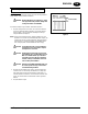
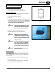
Level Indicators for the Charge of the Batteries
The battery meter ( see fi gure 7) on the control panel has a digital read out
with 10 fi xed positions (A) and also a blinking indicator (B). The bars that
appear on the display show the approximate charge level with icon (blink-
ing) discharged battery.
NOTE: A few seconds after the voltage reads 32V it will start blinking. The
brush motors will then automatically switch off.
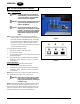
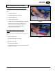
How To Install the Squeegee
To install the squeegee onto the machine, follow this procedure:
1. The squeegee assembly has a break away feature that is also used
for mounting the squeegee. Loosen the knobs on the squeegee
(fi gure 8). Slide the stud into the slotted hole in the support frame
on the machine.
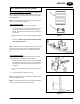
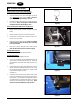
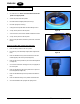
2. Attach the vacuum hose cuff to the squeegee hose fi tting (see fi gure
9).
3. Tighten knobs. NOTE: Do not overtighten or break away feature
is lost and damage may occur.
NOTE: To prevent damage to the squeegee or machine, the squeegee was
designed to break away from the machine. If the squeegee is impacted
and it breaks away from the machine, simply reinstall it by following step
1-3.
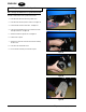
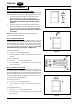
How to Adjust the Squeegee
During operation, the rear squeegee blade should have a constant 3/16”
minimum fl are along the entire squeegee blade (see fi gure 10).
1. The squeegee body can be tilted to adjust the squeegee blade fl are
in the middle to match the fl are on the ends. To adjust the tilt, loosen
the adjusting bolt located on the left and right side of the squeegee
(see fi gure 9).
2. Press down on the squeegee until both sets of guide wheels contact
fl oor.
3. After making adjustments, retighten the screw(s).
NOTE: It is important that the right and left wheels are contacting the fl oor
in order for the squeegee to work.
NOTE: As the rear squeegee blade wears, it can be rotated and/or fl ipped
to obtain four good edges before having to change blades.
Figure 7