E Operator's Manual Classic 8 Belt Sander READ THIS BOOK This book has important information for the use and safe operation of this machine. Failure to read this book prior to operating or attempting any service or maintenance procedure to your ALTO machine could result in injury to you or to other personnel; damage to the machine or to other property could occur as well. You must have training in the operation of this machine before using it.
Contents of this Book Operator Safety Instructions ........................................................ 3 Machine Safety Statements ......................................................... 5 Introduction and Machine Specifications ..................................... 6 230V Electrical Connection Instructions ...................................... 7 How to Transport the Machine..................................................... 8 One Person ...........................................................
OPERATOR SAFETY INSTRUCTIONS WARNING AVERTISSEMENT ADVERTENCIA DANGER means: Severe bodily injury or death can occur to you or other personnel if the DANGER statements found on this machine or in this Owner's Manual are ignored or are not adhered to. Read and observe all DANGER statements found in this Owner's Manual and on your machine.
DANGER: This machine had rotating and moving elements that can cause serious injury. Follow these precautions: • Do not operate this machine unless all guards, doors and covers are secure and in place. • Keep hands, feet and loose clothing away from all moving parts. • Do not service the machine while in operation. Disconnect the electrical cord before servicing. • Do not change or make adjustments to the abrasive while the machine is in operation.
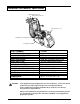
Machine Safety Statements The following safety decals are mounted on the machine as shown. If these or any other machine decal, label or plate should become damaged or illegible, install a new decal in its place. Contact your local authorized distributor for new decals. The following information signals potentially dangerous conditions to the operator and/or equipment. Read this manual carefully and familiarize yourself with the machine. Know when these conditions can exist.
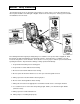
Introduction and Machine Specifications Operating Control Lever Motor Starter / Protector Tension Release Lever Sanding Pressure Adjustment Level Adjustment Nut PART NUMBER ABRASIVE SIZE CONTACT WHEEL SPEED ABRASIVE SPEED DUST FAN SPEED DUST FAN FLOW MOTOR LEVELING CONTROL OPERATING CONTROL MOTOR STARTER/PROTECTOR SANDING PRESSURE ADJUSTMENT WHEELS BEARINGS DIMENSIONS WEIGHT CAUTION: 07094C 291/2" x 7 7/8 " 2850 rpm (revolutions per minute) 4300 sfm (surface feet per minute) 6800 rpm (revolutions per
230V Electrical Connection Instructions CAUTION: This machine will operate only on AC frequency and on electrical voltage shown on the motor nameplate. Make sure you have the correct frequency and voltage before connecting the power cord to an outlet. The machine has a plug as shown below. Figure #1 This machine must be connected to an electrically ground circuit in order to protect the operator from electric shock.
How to Transport the Machine WARNING: The machine is heavy. Remove the motor from the machine before transporting. Get help loading the machine and motor. Transporting the Machine - One Person To transport the machine, follow this procedure: 1. Make sure the power cable is disconnected from the electrical outlet. 2. Disconnect the handle pigtail cord connection. (twist and pull) See figure #3. Figure 3 3. Loosen the belt tension T-screw completely.
NOTE: It is not necessary to adjust the fan belt independently during this procedure or during replacement. The idler pulley is factory adjusted. 5. Close the belt guard door. 6. Plug the motor pigtail in, twisting to lock. Transporting the Machine - Two People When transporting the machine with two people follow this procedure: 1. One operator places hands under the front of the machine main casting. 2.
Machine Set-Up To set-up your machine follow this procedure: 1. Familiarize yourself with the machine and read all danger, warning and caution statements. Make sure all operators of this machine have read this Owner's Manual. If they cannot read English, have the manual explained fully before allowing anyone to operate the sander. Figure 7 2. Locate the power supply. The receptacle should be compatible with the plug. The receptacle must be grounded and must be fused (30 amp) to avoid an electrical hazard.
How to Operate the Machine DANGER: Sanding/finishing wood floors can create an environment that can be explosive. Cigarette lighters, pilot lights and any other source of ignition can create an explosion when active during a sanding session. All sources of ignition should be extinguished or removed entirely if possible from the work area. DANGER: Work areas that are poorly ventilated can create an explosive environment when certain combustible materials are in the atmosphere, i.e.
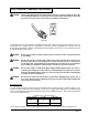
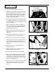
To operate the machine follow this procedure: 1. Install the operator's belt as follows: a. Position the operator's belt around waist. b. Cross the straps at the waist. See figure #11. c. Slide the belt loop end over the handle on the control lever side. Adjust the length as needed. d. Wrap the remaining strap around the opposite side of the handle and hold it in place with your hand.
A. First pass forward, right to left. B. First pass reverse, retrace same path. C. Second pass forward, overlap ½ the drum width. D. Second pass reverse, retrace second path forward, etc.....for the entire room. E. Work the remaining unsanded floor in the same fashion, right to left.
Sanding Cuts and Sandpaper Initial Cut The purpose of the initial cut is to remove old finish and gross imperfections on the floor surface. The sanding equipment should be adjusted to heavy sanding pressure setting and a coarse abrasive belt should be used. If the surface is severely damaged by deep scratches, pre-existing dwell marks, uneven planks, etc., it may be necessary to sand across or diagonally to the grain to restore evenness to the surface.
Sander Adjustment Procedures DANGER: Electrocution could occur if maintenance and repairs are performed on a unit that is not properly disconnected from the power source. Disconnect the power supply before attempting any maintenance or service. DANGER: Moving parts of this machine can cause serious injury and/or damage. Keep hands, feet and loose clothing away from all moving parts of the sander. The following information provides details on how to adjust different features/controls of the sander.
Leveling To adjust the machine leveling follow this procedure: 1. Locate the leveling screw. See figure #15. The leveling screw is located towards the rear of the chassis beneath the sanding pressure knob. 2. Tighten the leveling screw (compress the leveling spring) to sand heavier on the drive belt side. 3. Loosen the leveling screw (relax the leveling spring) to sand heavier on the side opposite the drive belts.
Routine Maintenance The following items need to be periodically inspected and maintained to keep your sander in good working condition. Sanding Chamber Periodically blow out the sanding chamber to prevent large accumulations of debris which could interfere with the performance of the tension roller. Wheels Periodically remove the debris from the truck and caster wheels. Debris can cause waves on a sanded surface.
Troubleshooting PROBLEM Drive belts slip. (Squeaking or squealing sound) CAUSE ACTION Insufficient tension. Tension drive belt as described in adjustment procedures. Worn belts. Replace belts. Squealing, growling or grinding noise coming from machine. Damaged and/or worn bearing. Remove drive belts, rotate arbor motor, fan, shafts and idler pulley to locate dragging or rough bearing. Contact an authorized dealer. Dust pick-up is poor. Dust bag is over 1/3 full. Empty contents of bag.
Troubleshooting PROBLEM Burning or glazing. ACTION CAUSE Dull abrasive. Replace abrasive. Excessive sanding pressure. Decrease sanding pressure setting. Fig. #14, page 13. Too fine of an abrasive. Use coarser abrasive. Dull abrasive. Replace abrasive. Too fine of an abrasive belt. Use a coarser abrasive belt. Insufficient sanding pressure. Increase sanding pressure setting. Fig. #14, page13. Debris on wheel. Remove and clean wheels. Flat spot on tire(s). Replace tires.
AMERICAN SANDERS TECHNOLOGY American Classic Sander 8 Assembly Drawing #1 11/00 8 3 7 4 5 2 6 39 1 9 11 52 10 38 40 12 41 37 36 42 14 35 13 45 44 15 16 46 17 18 19 43 20 49 21 50 22 47 51 23 48 24 25 27 29 30 19 34 26 31 33 51 30 29 28 32 Page 20 AMERICAN SANDERS TECHNOLOGY Classic 8 Operator's Manual
AMERICAN SANDERS TECHNOLOGY American Classic Sander 8 Assembly Parts List #1 11/00 Ref No. Part No 1 2 3 4 5 6 7 8 9 10 11 12 13 14 15 16 17 18 19 20 21 22 23 24 25 26 962727 22300AK 77057A 64506CK 85386A 980645 920260 65307A 86112A 65305A 65306A 67444A 51172A 61641A 51171A 57844A 66219A 980679 81106A 86110A 85834A 60421A 65309A 68395A 67868A 87033A Description Screw, 8-32 x ½ Door Access Label Belt Tracking Adj.
AMERICAN SANDERS TECHNOLOGY American Classic Sander 8 Tension Assembly Drawing 10/99 1 2 3 2 1 23 22 24 25 4 7 5 6 5 14 21 7 13 8 15 9 18 19 10 20 11 4 8 8 26 12 17 Page 22 16 AMERICAN SANDERS TECHNOLOGY Classic 8 Operator's Manual
AMERICAN SANDERS TECHNOLOGY American Classic Sander 8 Tension Assembly Parts List 10/99 Ref No. Part No 1 2 3 4 5 6 7 8 9 10 11 12 13 14 15 16 17 18 19 20 21 22 23 24 25 26 747380 902567 67201B 920296 81102A 80020A 14701A 81501A 66537A 50772A 50775A 797301 53410A 50719A 961014 61804A 65709A 80018A 87502A 87503A 65708A 81303A 60150A 61666A 67465A 980018 Description Retaining Ring 9/16 Bearing Roller Nut, 10-24 Nut, ¼-20 Shoulder Bolt, ¼ x 1 Guide, Roller Asm.
AMERICAN SANDERS TECHNOLOGY American Classic Sander 8 Assembly Drawing #2 11/00 78 2 9 8 4 3 12 11 1 47 6 79 10 7 74 15 14 16 13 5 17 18 19 20 70 73 21 22 69 76 71 72 23 24 68 78 75 25 26 67 27 28 66 29 30 65 31 32 33 53 61 64 34 35 59 60 52 58 57 56 41 36 55 54 49 51 50 44 62 48 45 46 43 42 63 37 40 40 Page 24 39 38 AMERICAN SANDERS TECHNOLOGY Classic 8 Operator's Manual
AMERICAN SANDERS TECHNOLOGY American Classic Sander 8 Assembly Parts List #2 11/00 Ref No Part No.
Page 26 15 11 16 17 112 111 18 12 13 116 117 115 113 164 14 110 114 73 134 662 67 66 120 119 174 676 59 168 169 161 160 133 63 124 164 59 16 149 150 149 AMERICAN SANDERS TECHNOLOGY Classic 8 Operator's Manual 150 148 138 152 157 153147 135 126 1 65 121 AMERICAN SANDERS TECHNOLOGY American Classic Sander 8 Assembly Drawing #3 11/00 58 72 118 127 128 127132 136 129 148 147 125 170 131 130 156 137 155 146 120141 144 142 146 120 142 138
AMERICAN SANDERS TECHNOLOGY American Classic Sander 8 Assembly Parts List #3 11/00 Ref. No Part No.
AMERICAN SANDERS TECHNOLOGY American Classic Sander 8 Wiring Diagram 7/93 Page 28 AMERICAN SANDERS TECHNOLOGY Classic 8 Operator's Manual
Chatter - Wave Prevention American Sanders Technology Sanders are designed and manufactured to the most rigid tolerances. However, after a finishing cut it is possible to see "chatter" or "waves". The best guarantee to remove the chatter is to finish the floor with a rotating horizontal sander, such as American Sanders Technology's Sander 16. To minimize chatter when using a belt sander the following steps should be taken: 1.) DRUM MARKS ....
5.) CONTACT WHEELS ....may become out of round or unbalanced and leave chatter. Contact your American Sanders Technology dealer if this problem should occur. 6.) BEARINGS ....in the motor, arbor shaft, or fan system, of poor quality or worn and damaged will leave chatter. "Play" in the bearing can provide enough motion to transfer to sanded surface to the point where chatter becomes visible. Contact your American Sanders Technology dealer if this problem should occur.
ALTO® PRODUCT SUPPORT BRANCHES U. S. A. Locations HEAD OFFICE European Locations PRODUCITON FACILITIES ALTO U.S. Inc., St. Louis, Missouri 390 S. Woods Mill Rd., Suite 300 Chesterfield, Missouri 63017-3433 PRODUCTION FACILITIES ALTO U.S. Inc., Springdale, Arkansas 2100 Highway 265 Springdale, Arkansas 72764 (501) 750-1000 Customer Service - 1-800-253-0367 Technical Service - 1-800-356-7274 ALTO U.S. Inc., Bowling Green, Ohio 43402 1100 Haskins ALTO U.S. Inc., Clearwater, Florida 33765 1500 N.
AMERICAN SANDERS TECHNOLOGY U. S. WARRANTY This ALTO Industrial/Commercial Product is warranted to be free from defects in materials and workmanship under normal use and service for a period of one year from the date of purchase, when operated and maintained in accordance with American Sanders Technology's Maintenance and Operations Instructions. This warranty is extended only to the original purchaser for use of the product. It does not cover normal wear parts such as electrical cable or V-belts.