E Operator's Manual Vision 21i VisionV READ THIS BOOK This book has important information for the use and safe operation of this machine. Failure to read this book prior to operating or attempting any service or maintenance procedure to your ALTO machine could result in injury to you or to other personnel; damage to the machine or other property could occur as well. You must have training in the operation of this machine before using it.
Table of Contents Operator Safety Instructions ............................................................................................................ 3 Introduction & Machine Specifications ............................................................................................. 5 Procedures For Transporting ............................................................................................................ 6 Symbols Used On Vision 21i & Vision V ..........................................
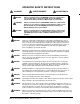
OPERATOR SAFETY INSTRUCTIONS WARNING AVERTISSEMENT ADVERTENCIA DANGER: Failure to read and observe all DANGER statements could result in severe bodily injury or death. Read and observe all DANGER statements found in your Owner's Manual and on your machine. WARNING: Failure to read and observe all WARNING statements could result in injury to you or to other personnel; property damage could occur as well. Read and observe all WARNING statements found in your Owner's Manual and on your machine.
WARNING: Maintenance and repairs performed by unauthorized personnel could result in damage or injury. Maintenance and repairs must be performed by authorized Clarke Technology personnel only WARNING: Any alterations or modifications of this machine could result in damage to the machine or injury to the operator or other bystanders. Alterations or modifications not authorized by the manufacturer voids any and all warranties and liabilities.
Introduction & Machine Specifications Introduction & Machine Specifications Clarke Technology’s newly designed Vision 21i & Vision V automatic scrubbers are efficient and superior floor cleaning machines. The Vision 21i uses two brushes or pads to scrub a path 21 inches wide. The Vision V uses two brushes or pads to scrub a path 26 inches wide. A squeegee wipes the floor while the vacuum motor removes the dirty solution from the floor - all in one pass.
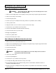
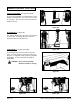
PROCEDURES FOR TRANSPORTING How To Put The Machine In A Van Or Truck WARNING: The machine is heavy. Make sure you use two able persons to assit the machine in climbing the ramp. 1. Make sure the loading ramp is at least eight (8) feet long, and strong enough to support the machine. 2. Make sure the ramp is clean and dry. 3. Put the ramp in position. 4. Remove squeegee assembly, brush housings, & brushes or pad drivers before loading. 5. Turn key switch "ON". 6.
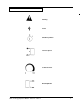
SYMBOLS USED ON VISION 21i & Vision V Warning Power On/Off Key Switch Traverse Speed Solution Control Brush Up/Down Clarke Technology Operator's Manual - Vision 21i - Vision V 7
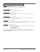
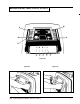
MACHINE CONTROL PANEL (Vision 21i & Vision V) Key Switch (See Figure #1, Item "A") The key switch turns "ON" the power to the control panel. "0" is "OFF" and "1" is "on". Traverse Speed Switch (See Figure #1, Item "B") The speed switch has three positions: High, Medium, and Low speeds. Brush Position Switch (See Figure #1, Item "C") The brush switch has two positions: "Up" positions the brushes up; "Down" positions the brushes on the floor. The brush motors start when the brushes are down.
MACHINE CONTROL PANEL (Vision 21i & Vision V) B C D A E F G H I J Figure #1 Figure #2 Clarke Technology Operator's Manual - Vision 21i - Vision V Figure #3 9
MACHINE CONTROLS & FEATURES Squeegee Lift Handle. See Figure #4a & #4b. The squeegee lift handle is located below the control handles on the right side. It is used to raise or lower the squeegee. The vac motor is turned on when the handle is lowered. Figure #4a Float Shut Off. See Figure #5. The shut-off switch for the vac motor is located in the recovery tank. It automatically turns off the vac motor when the recovery tank is full. Parking Brake. See Figure #6a & #6b. Figure #4b.
HOW TO PREPARE THE MACHINE FOR OPERATION How To Install The Batteries The Vision 21i and Vision V machines use four 6-volt or two 12-volt batteries. The batteries are located in the battery compartment under the recovery tank. To Install the batteries, follow this procedure: 1. Set the parking brake. Figure #7a 2. Make sure both tanks are empty. All 6 Volt Poly Case Batteries 3. Disconnect the hoses from the recovery tank (upper tank) & unplug the vac motor. Remove the recovery tank. 4.
HOW TO PREPARE THE MACHINE FOR OPERATION Battery Maintenance The electrical power to operate the machine comes from the storage batteries. Storage batteries need preventive maintenance. WARNING:Working with batteries can be dangerous. Always wear eye protection and protective clothing when working near batteries. NO SMOKING! To maintain the batteries in good condition, follow these instructions: 1. Keep the electrolyte at the correct level.
HOW TO PREPARE THE MACHINE FOR OPERATION How To Charge The Batteries WARNING: Charging the batteries in an area without adequate ventilation could result in an explosion. To prevent an explosion, charge the batteries only in an area with good ventilation. WARNING: Lead acid batteries generate gases which could explode. Keep sparks and flames away from batteries.
HOW TO PREPARE THE MACHINE FOR OPERATION How To Install The Brushes Or Pad Drivers To install the brushes or pad drivers on the machine, follow this procedure: 1. Engage the parking brake. 2. Turn the key switch "ON". 3. Put the brush switch in the "UP" position. 4. Turn the key switch "OFF". 5. Go to the front of the machine. 6. Pull out the brush housing pin and remove the right and left brush housings. Figure # 13 7. Put a brush or pad driver under the brush motor plate. See figure #13. 8.
HOW TO OPERATE THE MACHINE How To Operate the Squeegee The squeegee wipes the floor while the vacuum motor removes the dirty solution from the floor. Use your right hand to lower or raise the squeegee handle. To operate the squeegee, follow this procedure: 1. To lower the squeegee and start the vac motor move the squeegee lever to the right and down. See figure #14a. 2. To raise the squeegee, lift the squeegee lever up. See figure #14b.
HOW TO OPERATE THE MACHINE (cont.) WARNING: Water solutions or cleaning materials used with this type of machine can leave wet areas on the floor surface. These areas can cause a dangerous condition for the operator or other persons. Always put CAUTION signs near the area you are cleaning. WARNING: Machines can ignite flammable materials and vapors. Do not use with or near flammables such as gasoline, grain dust, solvents and thinners.
HOW TO OPERATE THE MACHINE (cont.) HOW TO CLEAN A FLOOR WARNING: Water solutions or cleaning materials used with this type of machine can leave wet areas on the floor surfaces. These areas can cause a dangerous condition for the operator or other persons. Always put CAUTION signs near the area you are cleaning. 3 To clean a floor, follow this procedure: 1. Set the parking brake. 2. Put the water and a cleaning chemical in the clean solution tank. 3. Release the parking brake. 4 4.
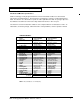
HOW TO CORRECT PROBLEMS IN THE MACHINE PROBLEM There is no solution flow. The solution flow does not stop. The machine does not remove all the water from the floor. CAUSE ACTION The solution valve is closed. Open the solution valve. There is an obstruction in the solution hose or filter. Remove the obstruction from the hose and the filter. The solution valve or linkage is damaged. Repair or replace the valve and the linkage. The solution tank is empty. Fill the solution tank.
PROBLEM The cleaning is not even. CAUSE ACTION The scrub brushes or pads are worn. Replace the scrub brushes or pads. There is damage to the brush assembly, casters or the solution valve. Have an authorized service person make the needed repairs. The brush motors are not running Check for tripped breaker, reset. Check for loose connections. The solution level is low. Fill the solution tank. NOTE: If the problem continues consult an authorized service person. The machine does not run.
MAINTENANCE WARNING: Maintenance and repairs must be done by authorized personnel only. WARNING: Always empty the solution tank and recovery tank before doing any maintenance. WARNING: Keep all fasteners tight. These Maintenance Procedures Must Be Done Every Day Keep the machine clean, it will need fewer repairs and have longer life. Figure #19 Do These Procedures When You Begin Your Work Period NOTE: Always engage the parking brake before servicing the machine. 1.
MAINTENANCE Do These Procedures When You End Your Work NOTE: Always engage the parking brake before servicing the machine. 1. Drain the solution tank (Figure #22a) and the recovery tank (Figure #22b). To drain the tanks , follow this procedure: a. Turn the key switch “OFF”. b. Remove the drain hose from the back of the machine. Figure #22a c. Put the end of the hose over a drain or bucket. d. Turn the valve handle to the left. Pull the handle out to open the drain.
MAINTENANCE These Maintenance Procedures Must Be Done Every Week: WARNING: Maintenance and repairs must be done by authorized personnel only. Always empty the solution tank and the recovery tank before doing any maintenance. Keep all fasteners tight. WARNING: Always wear eye protection and protective clothing when working near batteries. Do not put tools or other metal objects across the battery terminals or the tops of the batteries.
MAINTENANCE 7. Check the squeegee and the scrub brushes or the pad drivers for damage. 8. Check the squeegee and the vacuum hose for damage, leaks and obstructions. Maintenance For The Squeegee To remove the squeegee, follow this procedure: 1. Remove the squeegee assembly by loosening the two knobs that attach the squeegee to the machine. Pull the squeegee assembly off. See figure #25. Figure #25 2. Inspect the squeegee blade. 3.
MAINTENANCE Adjusting Squeegee Blades: When properly installed the front blade should be approximately .06 above the rear blade. See figure #28. Adjusting Squeegee Support Wheels: The support wheels should be set at .12 above the floor with the rear blade touching the floor. See figure #28. REAR BLADE .06 .12 Figure #28 WARNING: Maintenance and repairs must be done by authorized personnel only . WARNING: Electrical repairs must be done by authorized personnel only.
CLARKE TECHNOLOGY Vision 21i /Vision V Accessories - 11/95 Accessories: Description Power Wand System Kit ESP Recycle System Kit Soft Caster (Wheel only) Soft Traverse Wheel Low Voltage Shut-off (24v) Clarke Technology Care Kit Frame Bumper Roller Kit (one side per Kit) Part No. 14634A 14633A 52127A 59952A 14097A 14607A 821203 14693A Nitrile Squeegee Blades: Length 28.12" 32.50" Machine 21i Vision V Part No. 30938A 30949A Ribbed Squeegee Blades: Length 29.88" 25.88 Machine Vision V 21i Part No.
Page -26- 78 34 35 42 40 41 80 33 37 32 63 64 66 31 79 38 36 81 65 83 43 44 23 12 19 6 17 13 45 4 21 59 21 11 55 14 20 79 28 47 21 22 84 Clarke Technology Operator's Manual -Vision 21i - Vision V 47 7 82 27 23 16 8 15 30 75 4 3 54 46 1 50 4 63 23 89 2 3 67 87 88 48 57 71 776190 51 8560 18 55 65 49 72 62 56 70 85 48 85 53 23 ClLARKE TECHNOLOGY Vision 21i / Vision V Rear Cover Assembly Drawing 7/99 10 84 39 24 25 2 23 84 40 26 23 12
x x x x x x x x x x x x x x x x x x x x x x x x x x x x x x x x x x x x x x x x x x x x x x x x x x x x x x x x x x x x x x x x x x x x x x x x x x x x x x x x x x x Clarke Technology Operator's Manual - Vision 21i - Vision V Ref # 43 44 45 46 47 48 49 50 51 53 54 55 56 57 59 60 61 62 63 64 65 66 67 70 71 72 74 75 77 78 79 80 81 82 83 84 85 86 87 88 89 90 Part No.
14 33 16 35 34 30 16 40 22 42 39 41 21 1 23 38 24 37 36 3 2 43 4 26 31 29 9 7 8 6 5 19 30 27 28 2 20 7 24 5 10 4 18 11 25 12 25 32 7 16 17 15 19 13 CLARKE TECHNOLOGY Vision 21i - Vision V Traverse System Assembly Drawing 2/00 Page -28- Clarke Technology Operator's Manual -Vision 21i - Vision V
Ref # 1 2 3 4 5 6 7 8 9 10 11 12 13 14 15 16 17 18K 19 20 21 22 23 24 25K 26 27 28 29 30 31 32K 33 34 35 36 37K 38 39 40 41 42K NIK Part No.
CLARKE TECHNOLOGY Vision 21i - Vision V Squeegee & Squeegee Arm Assembly Drawing 1/97 34 11 ref.
Ref # 1 2 3 4 5 6 7 8 9 10 11 12 13 14 15 16 17 18 19 20 21 22 23 24 25 26 27 28 29 30 31 32 33 34 35 36 37 38 39 40 41 42 43 44 45 46 Part No.
CLARKE TECHNOLOGY Vision 21i - Vision V Brush Head Assemby Parts List 9/98 47 59 46 46 34 54 53 45 41 48 22 51 66 52 42 36 43 3 60 37 64 9 1 39 11 36 3 38 35 9 36 6 3 66 28 71 30 68 21 62 Squeegee Arm Stop Asm.
13 14 15 16 17 18 19 20 21 22 23 25 26 Part No. 962980 47374A 920056 47405A 85519A 69434A 81104A 46508A 82501A 68661A 68670A 782002 34705A 34704A 722030 980638 170915 962714 82508A 833802 962495 Pg 23 34400B 836711 838502 915102 45037A 27 28 29 30 31 32 33 34 35 36 41601A 920365 63058A 962344 67705B 41602A Pg. 33 38708A 67703A 82404A 11 12 Description Screw, 6-32 x 1 PN Lever Switch (Scrub Lmt.
CLARKE TECHNOLOGY Vision 21i - Vision V Solution/Vacuum System Drawing 9/98 8 24 36 34 33 40 47 41 2 32 35 8 37 38 48 51 52 17 39 56 2 53 50 54 32 8 17 31 25 27 24 17 30 2 28 24 43 26 29 42 23 20 55 34 8 22 27 21 2 20 19 16 13 18 5 14 15 12 16 6 5 3 7 9 8 6 5 2 4 Page -34- Clarke Technology Operator's Manual -Vision 21i - Vision V
2 3 4 5 6 7 8 9 10 11 12 13 14 15 16 17 18 19 20 21 22 23 24 25 26 27 28 Part No.
CLARKE TECHNOLOGY Vision 21i - Vision V Brush Housing Assembly Drawing 7/96 3 4 5 14 1 2 7 8 6 9 10 Page -36- 12 11 Clarke Technology Operator's Manual -Vision 21i - Vision V
Ref # 1 2 3 4 5 6 7 8 9 10 11 12 13 14 Part No. 64729A 64727A 64728A 64726A 81105A 980687 419702 85704A 69089A 69079A 38235A 38234A 50449A 38236A 38233A 69090A 69078A 81104A 81104A 85737A 85737A 81301A Description Brush Housing, L.H. Brush Housing, L.H. Brush Housing, R.H. Brush Housing, R.H. Nut, 3/8-16 ESNA Washer Guide, Wheel Scr., 3/8-16 x 2¼ Strap, R.H. Strap, R.H. Skirt, R.H. Skirt, R.H. Pin Skirt, L.H. Skirt, L.H. Strap, L.H. Strap, L.H. Nut, 1/4-20 ESNA Nut, 1/4-20 ESNA Scr., 1/4-20 x 5/8 Hex Scr.
CLARKE TECHNOLOGY Vision 21i - Vision V Alternate Brush Motor Assembly #44809A 5/95 NOTICE: If your Vision V or Vision 21i has brush motor #44809A, shown below, use the parts on this page. Refer to pages 30 and 31 in this manual for other parts. Ref. 1 2 3 4 Page -38- Part No. 980638 962244 44809A 53412A Description Washer, Lock 3/8 Screw, 3/8-16 x 3/4 Motor, Brush Head Pressure Spring Qty.
CLARKE TECHNOLOGY Vision 21i - Vision V Alternate Brush Motor #44809A 5/95 Flam Location Item 1 2 3 4 5 Part No. 56478A 50142A 902654 902550 51840A 6 7 8 9 10 11 12 13 14 15 16 17 50520A 56480A 962546 50517A 448396 40826A 55657A 55656A 59805A 50515A 44809A 54238A Description Stator Frame Assembly (w/Magnets & Clips) Armature Assembly (w. B.E. & F.E. Bearings) Bearings B.E. Bearing F.E.
CLARKE TECHNOLOGY Vision 21i - Vision V Brush Motor #45037A 3/95 Ref # 1 2 3 4 5 6 7 8 9 10 11 12 13 Page -40- Part No. 832315 980076 902547 50156A 902550 897655 830846 962955 50577A 833102 55133A 448396 40807A Description Qty Com. Bracket Cover 1 Washer - Helical 1 Bearing 1 Armature Assembly 1 Bearing 1 Seal - Oil 1 Bracket 1 Screw ¼-20 x 5¾ Hex 2 Bracket Assembly 1 Field Asm. w/Mag Clips 1 Brush Holding Asm.
CLARKE TECHNOLOGY Vision 21i - Vision V Traverse Motor #45038A 8/94 Ref # 1 2 3 4 5 6 7 8 9 10 11 Part No. 52776A 980076 902547 50156A 902550 897655 830845 962955 50577A 833102 912206 12 13 14 15 912207 55133A 448396 40807A Description Cover, Bracket, Com. Washer - Helical Bearing Armature Assembly Bearing Seal - Oil Bracket Screw ¼-20 x 5¾ Hex Bracket Assembly Field Asm.
CLARKE TECHNOLOGY Vision 21i - Vision V Battery Charger Drawing & Parts List 8/94 WARNING: All electrical repairs must be performed by qualified personnel only. Charger #40512A: 24 volt, 25 amp D.C., 115 volt, A.C., 60 Hz Charger #40513A: 24 volt, 25 amp D.C., 230 volt, A.C., 50 Hz Ref # 1 2 3 4 5 6 7 8 9 10 11 12 13 Page -42- Description Charger Case Transformer Electronic Controller Kit Capacitor, 660 V.A.C. Heat Sink Assembly Ammeter Fuse Holder Strain Relief, A.C. Cord Strain Relief, D.C. Cord D.C.
Clarke Technology Vision 21i - Vision V Vacuum Motor Model Drawing 8/94 Form # 44917A Ref # 1 2 * 3 4 5 6 7 * 8 9 * 10 11 * 12 13 Part No. Description Qty 51913A Clip (optional) 2 54809A Housing Vent 1 Fan 1 85303A Screw - 8x32 - 3/8 P.N. 4 40817A Brush, Mechanism 2 51914A Clamp 2 50618A Bracket,Commutator E.
CLARKE TECHNOLOGY Vision 21i - Vision V Electrical Schematic 7/99 Page -44- Clarke Technology Operator's Manual -Vision 21i - Vision V
CLARKE TECHNOLOGY Vision 21i and Vision V Connection Diagram 1/97 Front of Machine (Tank Removed) Clarke Technology Operator's Manual - Vision 21i - Vision V 45
CLARKE TECHNOLOGY Vision 21i and Vision V Connection Diagram 1/97 Rear of Machine (Rear cover open) Page -46- Clarke Technology Operator's Manual -Vision 21i - Vision V
CLARKE TECHNOLOGY Vision 21i and Vision V Connection Diagram 1/97 Inside Rear Cover Clarke Technology Operator's Manual - Vision 21i - Vision V 47
NOTES Page -48- Clarke Technology Operator's Manual -Vision 21i - Vision V
ALTO® PRODUCT SUPPORT BRANCHES U. S. A. Locations HEAD OFFICE European Locations PRODUCTION FACILITIES ALTO U.S. Inc., St. Louis, Missouri 390 S. Woods Mill Rd., Suite 300 Chesterfield, Missouri 63017-3433 PRODUCTION FACILITIES ALTO U.S. Inc., Springdale, Arkansas 2100 Highway 265 Springdale, Arkansas 72764 (501) 750-1000 Customer Service - 1-800-253-0367 Technical Service - 1-800-356-7274 ALTO U.S. Inc., Bowling Green, Ohio 43402 1100 Haskins ALTO U.S. Inc., Clearwater, Florida 33765 1500 N.
CLARKE TECHNOLOGY U.S. WARRANTY This ALTO Industrial/Commercial Product is warranted to be free from defects in materials and workmanship under normal use and service for a period of one year from the date of purchase, when operated and maintained in accordance with Clarke Technology's Maintenance and Operations Instructions.