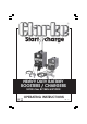
HEAVY DUTY BATTERY BOOSTERS / CHARGERS MODEL Nos.
Thank you for purchasing this CLARKE Battery Charger. These units are suitable for charging and boosting 12 Volt lead acid batteries. Model BC200N is also capable of charging 24 Volt batteries. Before attempting to operate the unit, please read this instruction manual thoroughly, and follow all directions carefully. By doing so you will ensure the safety of yourself, and others around you, and at the same time, you should look forward to the unit giving long and trouble free service.
IMPORTANT: SAFETY PRECAUTIONS PLEASE READ BEFORE USING THIS UNIT 1. WARNING: Some electronic equipment can be damaged by boost charging or use of start facility. Check your vehicle handbook before using your Start ’N’ Charge. If in doubt consult the vehicle manufacturer. Nevertheless, you should not operate this equipment unless you are fully conversant with vehicle electrical systems, and battery charging techniques. 2.
. ELECTRICAL CONNECTIONS BC185N WARNING! THIS APPLIANCE MUST BE EARTHED. Connect the mains lead to a 230 volt (50Hz) domestic electrical supply via a standard 13 amp BS 1363 plug fitted with a 13 amp fuse, or a suitably fused isolator switch.
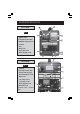
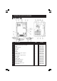
PARTS IDENTIFICATION BC185N FIG. 1 A - ON/OFF Switch B- Charge/Boost Start Switch C- MIN/MAX Charge Rate Sw. D - Ammeter E - Fuse F - Mains Lead G - RED, Positive Lead H - BLACK Negative Lead BC200N FIG.
ASSEMBLY The BC185N Charger/Booster is fully assembled, whereas the BC200N requires the wheel, foot and handle to be attached before use, as follows: 1. From the bag of loose parts, locate the four screws with washers and nuts with which to secure the foot to the base of the unit. Ensure the washers are at the screw heads. DO NOT fully tighten the nuts. Note that the foot is located at the front of the charger, the axle housing towards the rear. 2.
PROCEDURE FOR NORMAL CHARGING BC185N (Ref: Fig. 1). 1) Before charging or boosting, ensure that the cells are filled with electrolyte to the correct level by adding distilled water where necessary. 2) Where appropriate we recommend that the non-earthed lead on the battery is disconnected prior to charging. It is possible that damage may occur to any electronically controlled system fitted to the vehicle such as engine management, anti-theft alarm, alternator etc.
BC200N (Ref: Fig. 2). 1) Before charging or boosting ensure that the cells are filled with electrolyte to the correct level by adding distilled water where necessary. 2) Where appropriate we recommend that the non-earthed lead on the battery is disconnected prior to charging. It is possible that damage may occur to any electronically controlled system fitted to the vehicle such as engine management anti-theft alarm, alternator etc.
PROCEDURE FOR ENGINE STARTING BC185N (Re: Fig.1) Note: We recommend that before attempting to boost start you charge the battery for 10-15 minutes. This will improve the chance of a first time start, particularly with big engines. When the battery is completely flat, you must charge the battery for 10-15 minutes before attempting to start, otherwise you may cause damage to the vehicle electronic systems. a) Check that the ON/OFF switch (A) is in the OFF position.
PARTS LIST AND DIAGRAM BC185N No. 1 2 3 4 5 6 7 8 9 10 11 12 13 14 15 16 17 18 19 Description Qty Green Pilot Light Switch 16A-25uV Welding Current Switch 16A 250V Panel Panel Surround Ammeter Rectifier Panel Handle Compl. Thermostat + Support Cable Clamp Input Cable + Plug+13A Fuse Fuse Box Kit Fuse 120A Clamps 120A Black Cable 10 Sqmm Red Cable 10 Sqmm Thermostat Support Transformer 12/24V 230V Lower Panel 1 2 1 1 1 1 1 1 1 3 1 1 1 1 1 1 1 1 1 11 Part No.
PARTS LIST AND DIAGRAM BC200N No. Description Part No. No. Description Part No. 1 Upper Panel EM33705007 15 Black Cable EM43200014 2 Handle EM21600004 16 Earth Clamp 120A EM22110005 3 Back Panel EM33715037 17 Red Cable EM43200026 4 Rectifier Pms EM22400096 18 Dinse Plug EM22100001 5 Thermostat Compl. EM04600113 19 Orange Pilot-lamp EM22610012 6 Thermostat Support EM04600261 20 GreEM Pilot-lamp EM22610006 7 Lower Panel EM33700024 21 Wheel D.
WIRING DIAGRAMS BC185N BC200N 13
SPECIFICATIONS MODEL 185N 200N MAX CHARGE (AMPS) 22 30 MAX BOOST (AMPS) 180 200 BOOST/CHARGE (VOLTS) 12/24 12/24 BOOST START DUTY CYCLE Max 8 secs ON 30 secs OFF Max 10 secs ON 30 secs OFF THERMAL OVERLOAD PROTECTION YES YES 260X260X210 260X340X830 12.5 21 6261020 6261030 DIMENSIONS (LxWxH) mm. WEIGHT kg. PART NO. This battery charger is designed to charge either 12V or 24V lead-acid automotive batteries. Do not attempt to recharge any other type of battery.