Operator's Manual U.S. Patent No. 6,105,192; No. 6,557,207; No. 6,760,947; No. 5,383,251; & Patents Pending READ THIS BOOK CAUTION: Read the Operator's Manual before using the appliance. This book has important information for the use and safe operation of this machine. Failure to read this book prior to operating or attempting any service or maintenance procedure to your Clarke machine could result in injury to you or to other personnel; damage to the machine or to other property could occur as well.
Table of Contents Operator Safety Instructions ............................................................................................................................ 3 Introduction & Machine Specifications ............................................................................................................. 5 Procedures for Transporting Machine ............................................................................................................. 6 Symbols Used on Boost 28 ...............
OPERATOR SAFETY INSTRUCTIONS WARNING AVERTISSEMENT ADVERTENCIA DANGER: Failure to read and observe all DANGER statements could result in severe bodily injury or death. Read and observe all DANGER statements found in your Owner's Manual and on your machine. WARNING: Failure to read and observe all WARNING statements could result in injury to you or to other personnel; property damage could occur as well. Read and observe all WARNING statements found in your Owner's Manual and on your machine.
Page WARNING: Maintenance and repairs performed by unauthorized personnel could result in damage or injury. Maintenance and repairs must be performed by authorized Clarke personnel only. WARNING: Any alterations or modifications of this machine could result in damage to the machine or injury to the operator or other bystanders. Alterations or modifications not authorized by the manufacturer voids any and all warranties and liabilities.
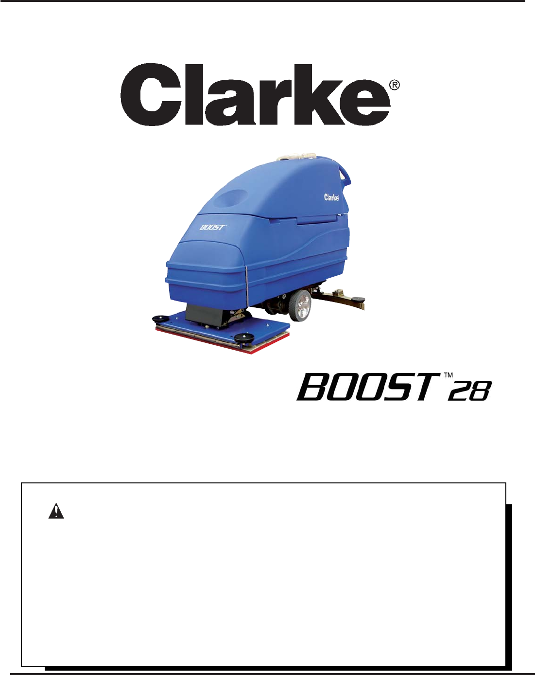
Introduction & Machine Specifications Introduction & Machine Specifications Clarke’s newly designed BOOST 28 automatic scrubber is an efficient and superior floor cleaning machine. The BOOST 28 uses an orbital movement to scrub a path 28 inches wide. A squeegee wipes the floor while the vacuum motor removes the dirty solution from the floor - all in one pass. The BOOST 28 comes complete with four - 6 volt batteries, one battery charger, a brush or a pad, and one operator’s manual.
Procedures For Transporting How to Put the Machine Into a Van or Truck WARNING: WARNING: This machine is heavy. Get assistance before attempting to transport or move it. Use two able persons to move the machine on a ramp or incline. Always move slowly. Do not turn the machine on a ramp. Do not stop and leave the machine on a ramp or incline. The loading ramp must be a minimum of 32" wide. Figure #1 Machines can topple over if guided over the edges of stairs or loading docks and cause injury or damage.
Procedures For Transpoting (cont.) 10. Fasten the machine to the vehicle. Clarke recommends a strap over the top of the machine and a strap to keep the machine from rolling forward or backwards. If this is not done, there is a possibility of the machine toppling over. Four tie down points (2 along each side of frame) are provided on machine for securing machine. How to Remove the Machine From a Van or Truck 1. Make sure there are no obstructions in the area. Figure #2 2.
SYMBOLS USED ON BOOST 28 Warning Solution Control Power Brush Up/Down Traverse Speed Control Warning Label with parking brake Page -8- Warning Label without parking brake Clarke® Operator's Manual - BOOST 28
Machine Control Panel Key Switch (See Figure 3, Item "A") The key switch turns "ON" the power to the control panel. "O" is "OFF" and "I" is "ON". Forward Reverse Switch (See Figure 3, Item "B") The forward/reverse switch turns the traverse motor "on" forward and if the brush motors are in the down position, activates the brush motor/solution control module. There is a two second delay for the pad motor to stop after releasing the switch. Either the right or the left switch can be used.
Machine Controls and Features Squeegee Lift Handle, See Figures 4 and 5 The squeegee lift handle is located below the control handles in the center. It is used to raise or lower the squeegee. The vac motor is turned on when the handle is lowered to either the first or last position. Float Shut Off, See Figure 6 The shut-off switch for the vac motor is located in the recovery tank. It automatically turns off the vac motor when the recovery tank is full.
How To Prepare the Machine For Operation How To Install The Batteries This machine uses either two 12-volt batteries or four - 6 volt batteries. The batteries are located in the battery compartment under the recovery tank. To install the batteries, follow this procedure: 1. Turn machine off. Set brake (if equipped). 2. Make sure recovery tank is empty. 3. Tip up the recovery tank until it locks in the full open position. See figure 8A. CAUTION: Before raising the tank, be sure tank is empty.
How To Prepare the Machine For Operation Battery Maintenance The electrical power to operate the machine comes from the storage batteries. Storage batteries need preventative maintenance. WARNING: Correct Level Working with batteries can be dangerous. Always wear eye protection and protective clothing when working near batteries. NO SMOKING! To maintain the batteries in good condition, follow these instructions: Figure 10 1. Keep the electrolyte at the correct level.
How To Prepare the Machine For Operation How To Charge The Batteries WARNING: Charging the batteries in an area without adequate ventilation could result in an explosion. To prevent an explosion, charge the batteries only in an area with good ventilation. WARNING: Lead acid batteries generate gases which could explode. Keep sparks and flames away from batteries. NO SMOKING! To charge the batteries, follow this procedure: 1. Make sure the key switch is in the “OFF” position. 2.
How To Prepare the Machine For Operation How To Charge The Batteries (On-Board Charger Option) WARNING: Charging the batteries in an area without adequate ventilation could result in an explosion. To prevent an explosion, charge the batteries only in an area with good ventilation. WARNING: Lead acid batteries generate gases which could explode. Keep sparks and flames away from batteries. NO SMOKING! To charge the batteries, follow this procedure: 1. Make sure the key switch is in the “OFF” position. 2.
How To Prepare the Machine For Operation How To Install The Brush Or Pad To install the brush or pad on the machine, follow this procedure: 1. Turn the key switch "ON". 2. Put the brush switch in the "Up" position. 3. Turn the key switch "OFF". 4. Go to the front of the machine. 5. Press on a brush or pad, under the flex plates. See figure 13. Figure 13 NOTE: When using a black pad, position pad on head.
How To Operate The Machine How To Operate The Squeegee The squeegee wipes the floor while the vacuum motor removes the dirty solution from the floor. Use your hand to lower or raise the squeegee handle. To operate the squeegee, follow this procedure: 1. To lower the squeegee and start the vacuum motor, move the squeegee lever to the right and down. See figure 15. 2. To raise the squeegee, lift the squeegee lever up. See figure 16.
How To Operate The Machine WARNING: Water solutions or cleaning materials used with this type of machine can leave wet areas on the floor surface. These areas can cause a dangerous condition for the operator or other persons. Always put CAUTION signs near the area you are cleaning. B C A A WARNING: Machines can ignite flammable materials and vapors. Do not use with or near flammables such as gasoline, grain dust, solvents and thinners.
How To Operate The Machine (cont) How To Clean A Floor WARNING: Water solutions or cleaning materials used with this type of machine can leave wet areas on the floor surfaces. These areas can cause a dangerous condition for the operator or other persons. Always put CAUTION signs near the area you are cleaning. To clean a floor follow this procedure: 1. Set the parking brake (if equipped with machine.) 2. Put the water and a cleaning chemical in the clean solution tank. 3.
Maintenance WARNING: Maintenance and repairs must be done by authorized personnel only. WARNING: Always empty the solution tank and recovery tank before doing any maintenance. WARNING: Keep all fasteners tight. These Maintenance Procedures Must Be Done Every Day Keep the machine clean, it will need fewer repairs and have longer life. Figure 20 Do These Procedures When You Begin Your Work Period 1. Turn off key switch. 2. Disconnect AC power from battery charger (follow charger instructions). 3.
Maintenance Do These Procedures When You End Your Work 1. Drain the solution tank (Figure 23) and the recovery tank (Figure 24). To drain the tanks , follow this procedure: a. Turn the key switch “OFF”. b. Remove the drain hose from the back of the machine. c. Put the end of the hose over a drain or bucket. d. Recovery Tank: 1.) Turn the valve handle to the left. Pull the handle out to open the drain (Figure 25).
Maintenance Maintenance Procedures To Be Done Every Week: WARNING: Maintenance and repairs must be done by authorized personnel only. Always empty the solution tank and the recovery tank before doing any maintenance. Keep all fasteners tight. WARNING: Always wear eye protection and protective clothing when working near batteries. Do not put tools or other metal objects across the battery terminals or the tops of the batteries.
Maintenance Maintenance For The Squeegee To remove the squeegee, follow this procedure: 1. Remove the squeegee assembly by loosening the two knobs that attach the squeegee to the machine. Pull the squeegee assembly off. See figure 29. 2. Inspect the squeegee blade. 3. If the blade is worn, turn the blade so that a new edge is in the wiping position. Figure 29 4. Reinstall squeegee assembly on the machine.
Maintenance cont. Consult your Clarke Authorized Service Person to do the service procedures. Use only genuine Clarke parts. How to Center or Offset the Brush Head 1 2 The brush head on this machine can be centered or offset 1 inch to the right side of the machine. To center or offset the brush head, follow this procedure: 3 Recommended tools: 3/8" drive rachet, 3" extension and 9/16" socket. CAUTION: 4 Before offsetting the brush head, be sure that the recovery tank is empty of solution. 1.
Accessories ACCESSORIES Description Power Wand System Kit Clarke Care Kit 39" Squeegee Assembly Poly Dur Protectant Kit, Grease Gun Kit, Low Voltage Shut-Off Brake Kit Assembly Accessory Bag Hour Meter Kit Soft Caster Assembly Kit, Solution Fill ESP Recycle System Brushes and Pads: Size Description 14 x 28 Red (5 pack) 14 x 28 Black (5 pack) 14 x 28 White (5 pack) 14 x 28 Blue (5 pack) Squeegee Blades: Description Blade, Rear - Gum Rubber Blade, Rear - Nitrile Solid Blade, Rear - Ribbed Orange Blade, Fro
HOW TO CORRECT PROBLEMS IN THE MACHINE PROBLEM There is no solution flow. The solution flow does not stop. The machine does not remove all the water from the floor. The batteries do not give the normal running time. Clarke® Operator's Manual - BOOST 28 CAUSE ACTION The solution tank is empty. Fill the solution tank. The solution valve is closed. Open the solution valve. There is an obstruction in the solution hose or filter. Remove the obstruction from the hose or filter.
PROBLEM The cleaning is not even. CAUSE ACTION The scrub brush or pad is worn. Replace the scrub brush or pad. There is damage to the brush assembly, caster or the solution valve. Have an authorized service person make the needed repairs. The brush motor is not running Check for tripped breaker. Reset. Check for loose connections. The solution level is low. Fill the solution tank. NOTE: If the problem continues consult an authorized service person. The machine does not run.
Section II Parts and Service Manual (71071A) U.S. Patent No. 6,105,192; No. 6,557,207; No. 6,760,947; No. 5,383,251; and patents pending.
Clarke® 33 34 Final Assembly Drawing 9/05 4 39 32 35 36 On-Board Charger Option 37 5 15 11 38 6 4 4 2 3 5 6 31 28 27 30 26 27 32 7 29 15 4 25 9 8 24 10 11 8 23 22 20 19 9 21 8 10 11 8 12 18 17 13 14 16 8 10 11 Page -28- Clarke® Operator's Manual - BOOST 28
Clarke® Re Ch mot ar e ge r O nB Ch o a r ard ge r Final Assembly Parts List 9/05 Ref. # 1 2 3 4 5 6 7 8 9 10 11 12 13 14 15 16 17 18 19 20 21 22 23 24 25* 26 27 28 29 30 31 32 33 34 35 36 37 38 39 NI NI NI NI NI Part No.
Clarke® Recovery Tank Assembly Drawing 9/05 1 2 43 3 4 5 42 41 6 8A 43 7 40 8B 9 8 10 39 38 37 36 35 20 19 7 34 12 18 17 16 26 18 27 30 16 14 28 33 13 11 15 31 25 32 24 23 29 21 22 #40 Recommended Torque 175 + or - 5 inch pounds Page -30- Clarke® Operator's Manual - BOOST 28
Clarke® Recovery Tank Assembly Parts List 9/05 Ref. # 1 2 3 4 5 6 7 8 8A 8B 9 10 11 12 13 14 15 16 17 18 19 20 21 22 23 24 25 26 27 28 29 30 31 32 33 34 35 36 37 38 39 40 41 42 43 NI NI Part No.
Clarke® Solution Tank Assembly 9/05 25 19 24 21 20 23 2 18 1 17 16 15 3 12 8 4 5 6 5 5 7 11 5 Page -32- Clarke® Operator's Manual - BOOST 28
Clarke® Solution Tank Assembly Parts List 9/05 Ref. # 1 2 3 4 5 6 7 8 11 12 13 15 16 17 18 19 20 21 23 24 25 NI NI Part No.
Clarke® Rear Panel Assembly Drawing 9/05 Remote Charger 1 2 1 2 5 4 3 35 6 7 34 32 33 8 9 9 10 31 10 9 10 6 29 28 3 11 27 3 10 15 30 11 16 17 16 15 36 26 25 24 18 14 21 20 19 13 2 22 12 23 Page -34- Clarke® Operator's Manual - BOOST 28
Clarke® Rear Panel Assembly Parts List 9/05 Remote Charger Ref. # 1 2 3 4 5 6 7 8 9 10 11 12 13 14 15 16 17 18 19 20 21 22 23 24 25 26 27 28 29 30 31 32 33 34 35 36 NI NI Part No.
Clarke® Rear Panel Assembly Drawing 9/05 On-Board Charger 2 1 1 2 5 4 3 35 6 7 34 32 33 8 9 9 10 31 10 9 10 36 27 3 15 30 11 41 42 41 16 17 16 15 37 26 25 24 18 27 14 12 21 20 2 19 13 41 11 29 22 39 23 38 28 40 23 2 Page -36- Clarke® Operator's Manual - BOOST 28
Clarke® Rear Panel Assembly Parts List 9/05 On-Board Charger Ref. # 1 2 3 4 5 6 7 8 9 10 11 12 13 14 15 16 17 18 19 20 21 22 23 24 25 26 27 28 29 30 31 32 33 34 35 36 37 38 39 40 41 42 NI NI Part No.
Clarke® Control Panel Assembly Drawing 9/05 1 2 4 7 3 8 11 12 37 5 34 6 35 36 27 36 29 38 11 10 14 7 28 33 32 31 30 19 27 18 1516 15 16 26 16 25 39 16 15 15 17 5 2 5 24 23 20 9 21 Page -38- Clarke® Operator's Manual - BOOST 28 3
Clarke® Control Panel Assembly Parts List 9/05 Ref. # 1 2 3 4 5 6 7 8 9 10 11 12 13 14 15 16 17 18 19 20 21 23 24 25 26 27 28 29 30 31 32 33 34 35 36 37 38 39 NI NI Part No.
Clarke® Squeegee Lift Assembly Drawing 9/05 15 1 20 21 19 10 6 12 22 3 4 17 5 6 15 15 16 8 9 7 8 2 14 13 11 18 Page -40- Clarke® Operator's Manual - BOOST 28
Clarke® Squeegee Lift Assembly Parts List 9/05 Ref. # 1 2 3 4 5 6 7 8 9 10 11 12 13 14 15 16 17 18 19 20 21 22 Part No.
Clarke® Squeegee Assembly Drawing 9/05 1 2 21 21 5 3 19 4 5 4 18 20 21 7 17 8 9 10 11 12 13 22 16 Page -42- 14 15 Clarke® Operator's Manual - BOOST 28
Clarke® Squeegee Assembly Parts List 9/05 Ref. # 1 2 3 4 5 6 7 8 9 10 11 12 13 14 15 16 17 18 19 20 21 22 Part No.
Clarke® Frame Axle Assembly Drawing 9/05 28 26 27 29 22 22 16 1 16 2 25 4 31 24 3 5 6 21 32 23 19 8 7 22 4 3 2 19 18 30 11 8 13 10 11 9 13 Page -44- Clarke® Operator's Manual - BOOST 28
Clarke® Frame Axle Assembly Parts List 9/05 Ref. # 1 2 3 4 5 6 7 8 9 10 11 12 13 14 15 16 17 18 19 21 22 23 24 25 26 27 28 29 30 Part No.
Clarke® Brush Head Assembly Parts List 9/05 55 56 Page -46- Clarke® Operator's Manual - BOOST 28
Clarke® Brush Head Assembly Parts List 9/05 Ref. # 1 2 3 4 5 6 7 8 9 10 11 12 13 14 15 16 17 18 19 20 NI 21 22 23 24 25 26 27 28 29 30 31 32 33 34 35 36 37 38 39 40 41 42 43 44 45 46 47 48 49 50 51 52 53 54 55 56 Part No.
Clarke® Optional Brake Drawing and Parts List 9/05 Drawing # 10072A 4 5 3 6 2 7 1 8 Ref # 1 2 3 4 5 6 7 Part No. 50981A 60388A 30095A 80123A 80125A 30094A 80124A 8 10160A Description Spacer Tie, Cover Retainer Nut, Brake Drive Key, 3/32 Sq. x 1/4 Lg. Cover, Vinyl Screw Set (Brake Nut to Motor Shaft) Brake, Asm. 24V Qty 1 1 1 1 1 2 1 NOTE: Only use spacer (ref. #2) on transaxles that have a circular step and mounting nuts protruding from end of motor.
Clarke® Vacuum Motor Drawing and Parts List 9/05 PARTS LIST DESCRIPTION 1. HOUSING 2. SCREW 3. FAN 4. COMM END BRACKET 5. BRUSH MECHANISM 6. LOAD SPRING 7. BALL BEARING 8. SCREW 9. ARMATURE 10. FIELD 11. BALL BEARING 12. NEOPRENE WASHER 13. FAN END BRACKET 14. SPACER 15. FAN 16. ROTATING FAN 17. SPACER 18. STATIONARY FAN 19. ROTATING FAN 20. STATIONARY FAN 21. ROTATING FAN 22. FAN SHELL 23. WASHER 24. NUT 25.
Clarke® Transaxle Drawing 9/05 Page -50- Clarke® Operator's Manual - BOOST 28
Clarke® Battery Charger Drawing and Parts List 9/05 WARNING: All electrical repairs must be performed by qualified personnel only. Charger #40512A: 24 volt, 25 amp D.C., 115 volt, A.C., 60 Hz. Charger #40513A: 24 volt, 25 amp D.C., 230 volt, A.C., 50 Hz Ref. No. 1 2 3 4 5 6 7 8 9 10 11 12 13 Description Charger Case Transformer Electronic Controller Kit Capacitor, 660 V.A.C. Heat Sink Assembly Ammeter Fuse Holder Strain Relief, A.C. Cord Strain Relief, D.C. Cord D.C. Cord Assembly A.C.
Clarke® Connection Diagram 9/05 Page -52- Clarke® Operator's Manual - BOOST 28
Clarke® Electrical Schematic 9/05 Clarke® Operator's Manual - BOOST 28 Page -53-
NOTES Page -54- Clarke® Operator's Manual - BOOST 28
CLARKE PRODUCT SUPPORT BRANCHES U. S. A.
Clarke® LIMITED U.S. WARRANTY This Clarke Industrial/Commercial Product is warranted to be free from defects in materials and workmanship under normal use and service, when operated and maintained in accordance with Clarke's Maintenance and Operations instructions. The warranty period is subject to the conditions stated below.