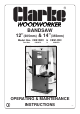
BANDSAW 12”(305mm) & 14”(355mm) Model Nos. CBS12WC & CBS14WC Part Nos.
Thank you for selecting this CLARKE Bandsaw . Before attempting to operate the machine, please read this instruction manual thoroughly, and follow all directions carefully. By doing so you will ensure the safety of both yourself and others around you, and at the same time, you should look forward to the Bandsaw giving you long and trouble free service. GUARANTEE This CLARKE product is guaranteed against faulty manufacture for a period of 12 months from the date of purchase.
11. DRUGS, ALCOHOL, MEDICATION. Do not operate machine while under the influence of drugs, alcohol or any medication. SAFETY PRECAUTIONS GENERAL SAFETY RULES FOR OPERATING MACHINERY 12. USE RECOMMENDED ACCESSORIES. The use of improper accessories could be hazardous. WARNING: 13. NEVER LEAVE MACHINE RUNNING UNATTENDED. Turn power OFF. Do not leave the machine until it comes to a complete stop. As with all machinery, there are certain hazards involved with their operation and use.
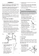
ELECTRICAL INSTALLATION ADDITIONAL SAFETY RULES FOR BANDSAWS • • • • • • • • • • • Connect the mains lead to a standard, 230 Volt (50Hz) electrical supply through an approved 13 amp BS 1363 plug, or a suitably fused isolator switch. Use a Push Stick or scrap of wood to do the pushing and guiding, when sawing small pieces which require the fingers to be close to the blade. Set the blade guide block assembly as close as possible to the workpiece.
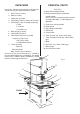
UNPACKING PRINCIPAL PARTS Unpack the shipping carton and lay out all the items so that they may be clearly identified as follows: (Ref. Fig. 1) A Blade Tension Adjuster Knob 1. Main Frame Assembly B Blade Guard and Upper Guide Block Securing Knob. NOTE: This item is mounted on the back panel, on model CBS12WC, as indicated by the dotted line. 2. Motor Assembly 3. Switch Box Assembly 4.
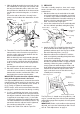
3. Remove the nuts and washers from the motor mounting studs. ASSEMBLY Plan your installation. Ensure adequate floor space is available, with good lighting and ventilation, and an adequate electrical supply is close at hand. 4. Place the motor on to the studs, with the pulley through the hole in the casing. DO NOT replace the nuts or washers at this point. Any protective coating on the Band Saw should be removed using a cloth moistened with paraffin. DO NOT use acetone, petrol or paint thinners. 5.
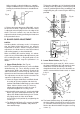
3. With the blade located in the centre hole, line up the slotted holes of the larger rear trunnion, with the long and short table tubes, and at the same time position the slotted hole in the front trunnion into the other end of the long tube, as shown in fig 5. Ensure the ends of the tubes sit neatly in the grooves on the inside of the slotted holes in each trunnion. Fig. 5 Rear Trunnion Long Table Tube 2.
D. ELECTRICAL CONNECTIONS ADJUSTMENTS 1. Switch Box A. BLADE ALIGNMENT AND TENSION On the left hand side of the frame, between the upper and lower wheel covers, are two loosely fitted screws. These are the mountings for the switch box. Blade tension is effected by raising or lowering the upper wheel, by means of the Blade Tension Adjuster Knob (A, fig. 1) The upper wheel is mounted on a spring loaded trunnion, and tension is therefore a matter of ‘feel’.
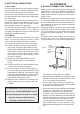
This bearing should be set 1/64” (0.04mm) behind the blade, and is adjusted by slackening the grub screw (E), positioning the bearing accordingly, and re-tightening the grub screw using the Allen key provided. Adjust carefully so that the blade runs smoothly along the middle of the tyre, and lock the alignment knob in place with the locknut on its threaded shaft. (see fig. 9) Adjuster Knob Fig. 9 Fig 10 D E Locknut 4.
2.3 Slacken the grub screw (H), which secures the shaft carrying The Blade Guide Bearing (D), and adjust the position of the bearing so that it is1/64” behind the blade (as shown in fig. 10). Re-tighten the grub screw, using the Allen key provided BLADE RENEWAL 1. Disconnect the mains cable from the supply. 2. Slacken off blade tension using the adjuster knob on top of the machine. 3. Raise the upper blade guard and guide block to the top of its travel, and secure in position. C. TABLE ADJUSTMENTS 4.
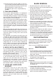
BLADE GUIDES FREEHAND SAWING Blade guides should be inspected regularly for wear or chipping. When replacing guides replace all guides at the same time, both upper and lower. The ease with which many different and varied shapes can be cut is one of the most important features of the bandsaw. Select a blade suitable for cutting the smallest radius in the work you have planned. See your CLARKE dealer for replacement or alternative blades.
PARTS LIST & DIAGRAM FLOOR STAND (Optional) Part No. 6460075 1 2 3 4 5 6 7 8 9 10 11 Stand Top Screw 3/8” Leg Brace - Side Brace Front and Rear Bolt Cap Hd. Sq. Shoulder Hex. Nut 5/16” Washer Hex. Nut 14” Foot - Rubber Pad Screw FMEBS14S01 FMEBS14S02 FMEBS14S03 FMEBS14S04 FMEBS14S05 FMEBS14S06 FMEBS14S07 FMEBS14S08 FMEBS14S10 FMEBS14S11 FMEBS14S12 FLOOR STAND SPECIFICATIONS Dimensions 710 x 540 x 550mm Weight 13 kg SPECIFICATIONS CBS12WC CBS14WC Motor ..............................................
CBS12WC PARTS LIST No.
PARTS DIAGRAM CBS12WC 14
PARTS LIST CBS14WC No. Description Part No. No. Description Part No.
PARTS DIAGRAM CBS14WC 16
PARTS DIAGRAM CBS14WC 17