METAL LATHE - CL430 & LATHE/MILL DRILL - CL500M OPERATING & MAINTENANCE INSTRUCTIONS 1 1105
DISCLAIMER This manual is intended to instruct the user on the operations peculiar to the CL430 Lathe and CL500M Lathe/Mill Drill ONLY. Although some reference is made, and advice given, regarding various metal turning techniques, it should not be regarded as a general tutorial on the subject. It is assumed that the user has some knowledge of machinery of this type, and is familiar with metal turning and milling . If this is not the case, we strongly advise that he/she seek advice from a qualified person.
INTRODUCTION Thank you for purchasing this CLARKE Lathe. Model CL430M comprises the lathe only, whereas the CL500M comprises the lathe with Mill Head, making it a complete machine centre. Please note that it is not possible to add a Mill Head to the CL430M, to convert it to a CL500M, at a later date. The flat lathe bed is solidly constructed from cast iron giving it exceptional rigidity and stability, making it an ideal tool for general turning operations.
TABLE OF CONTENTS PAGE Guarantee ............................................................................................ 3 Specifications ....................................................................................... 5 General Safety Precautions ............................................................... 5 Additional Safety Rules for Metal Lathes .......................................... 7 Unpacking and Installation ................................................................
SPECIFICATIONS LATHE Motor .................................................................... 230VAC, 50Hz, 1 Phase Power Rating ............................................... 3/4HP Fuse Rating .................................................. 13Amps Distance Between Centres ................................. 430mm Centre Height ....................................................... 150mm Max. Work Diameter over Bed ........................... 305mm Max. Work Diameter over Cross Slide ...............
GENERAL SAFETY PRECAUTIONS FOR OPERATING MACHINERY CAUTION As with all machinery, there are certain hazards involved with their operation and use. Exercising respect and caution will considerably lessen the risk of personal injury. However, if normal safety precautions are overlooked or ignored, personal injury to the operator or damage to machinery may result. 1. KNOW YOUR MACHINE. Read the manual carefully.
18. DO NOT STAND ON THE MACHINE. Serious injury could occur if the machine is tipped over. Do not store materials above or near the machine such that it is necessary to stand on the machine to get to them. 19. NEVER operate a machine when under the influence of alcohol, drugs or medication. 20. ALWAYS ENSURE THAT ADEQUATE LIGHTING is available. A minimum intensity of 300 lux should be provided. Ensure that lighting is placed so that you will not be working in your own shadow.
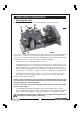
UNPACKING & INSTALLATION Mounting the Lathe On receipt, carefully remove the wooden casing to expose the lathe. Fig.1 Fig.1, shows model CL500M. Model CL430 is similar, but does not include the Mill Head - shown at ‘A’. CL430 users should therefore ignore all reference to the Mill Head . Inspect to ensure that no damage was suffered during transit. Should any damage be apparent, please contact your Clarke dealer immediately. • Carefully remove the Mill Head Pulley Cover ‘B’.
• Four holes are provided in the bed, for mounting purposes. Use suitable M10 bolts (not supplied) with flat washers, ensuring they are tight. At the leadscrew side of the bed, it will be necessary to thread the mounting bolts up through the bed then screw on the washers and nuts. NOTES: Ensure the location is adequately lit and that you will not be working in your own shadow. Ensure an adequate power supply is close at hand. DO NOT allow cables to trail on a workshop floor.
• Fit the Chuck Guard according to Fig.5. Fig.5 CL500M: Remove the transit screw in the base of the Mill Head from the position arrowed at ‘B’, (if fitted). Secure the Stop Bar ‘A’ with the screw and flat washer ‘B’ found in the guard kit. The screw attached to the Guard ’C’ is threaded through the remaining hole in the stop bar, and screwed into the headstock....note the rounded end of the stop bar is at the guard pivot end...or to the right side.
Fig.8 • Slide the Arbor into the spindle and push home - fully (Fig.8)...... Fig.9 .....then screw the Draw Bar (‘A’Fig.9), down through the spindle and into the arbor - fully. Secure by tightening the locknut (‘B’ Fig.9). • The chuck may now be located on the morse tapered arbor. Tap home using a block of wood ONLY. • Screw the Spindle Cover (‘C’ Fig.9) into the pulley cover and place the cap on top • Screw the two handles (‘C’ Fig.10) into the spindle feed hub and tighten. Fig.10 A ....
• Fit the Chuck Guard as follows: Fig.11 a. Unscrew and remove the spindle sleeve locating peg from the front of the mill head shown at ‘H’, Fig. 10. b. Screw the Guard Support assembly (‘A’ Fig. 11) - to be found in the box of loose parts, into the hole vacated by the locating peg, until it binds. Back off approx. one quarter of a turn and lock in place with the locknut. The support bar should be perpendicular, as shown. c.
ELECTRICAL CONNECTIONS CAUTION! DO NOT ATTEMPT TO USE THE MACHINE UNTIL INSTALLATION IS COMPLETED, AND ALL PRELIMINARY CHECKS HAVE BEEN MADE IN ACCORDANCE WITH THIS MANUAL. Connect the mains lead to a standard, 230 Volt (50Hz) electrical supply through an approved 13 amp BS 1363 plug, or a suitably fused isolator switch.
FEATURES Fig.13 1 Mill Head 17 Compound Slide Feed Handle 2 Mill Head Locking Lever 18 Cross Slide 3 Mill Head Elevating Lever 19 Saddle 3a Mill Head Elevating Collar 20 Cross Slide Feed Handle 4 Pulley Cover securing Knob 21 Leadscrew 5 Spindle Cover (2-part) 22 Leadscrew Locking Lever 6 Spindle Micro Feed Knob 23 Saddle Feed Handle.
THE HEADSTOCK The Motor drives the spindle via drive belts, which may be configured to provide 6 speeds. A three jaw self centering chuck is fitted, and may be removed by unscrewing the three bolts securing it to the spindle flange, so that optional accessories may be used, such as a Face Plate for use with the MT4 Centre provided, or an independent 4-Jaw chuck. Three external jaws are supplied to extend the capacity of the 3-jaw chuck. The method of assembly is described on page 25.
The cross-slide and compound slide feeds are provided with a scale. These are used to move the tool by precise amounts - one division being equivalent to 0.001” (0.025mm). As the feed handle is turned, so does the scale. The scale on the crossslide feed may also be held stationary whilst the handle is turned, allowing the scale to be ‘zeroed’. The manner in which this is put to use is discussed in greater detail under ‘Operation’.
PREPARATION FOR USE A. SIMPLE TURNING The following notes are guidelines as to how to set up the lathe in order to carry out a simple turning operation. ALWAYS plan your work. Have drawings or a plan on hand together with any measuring instruments you may require, such as micrometers/verniers/callipers etc. 1. Set Spindle speed Determine the speed required for the job in hand, and, consulting the chart on the inside of the running gear cover door, duplicated in Fig.
2. Mount the Cutting Tool Select a cutting tool that will produce the desired cut and mount it in the Tool Rest, with as little overhang as possible, securing it using three hex socket head screws. (Ideally, the overhang should be approx. 10 mm but not more than 15mm for a straight tool). It is IMPORTANT to ensure that the tip of the cutting tool is on the centre line of the work, or very slightly below it. On no account should it be above the centre line.
B. SIMPLE TURNING WITH POWER FEED The same basic setup is used as for simple turning, except that, before starting, the 2-Speed Lever is set to either 1 or 2 in order to provide the desired feed rate. CAUTION: NEVER attempt to change speeds whilst the machine is operating. As mentioned previously, the rotational speed of the leadscrew, and hence the rate of feed of the tool, is dependant upon the gear train configuration.
The taper, or bevel, is cut by setting the cross slide appropriately then using the compound slide feed handle to advance the cutting tool in the direction of the arrow as shown in Fig.18. Fig.19 D. SCREW CUTTING This operation requires a degree of skill and accuracy, and should not be attempted unless you are completely familiar with all aspects of the lathe.
CHANGING GEARS FOR SCREW CUTTING The leadscrew is driven via a gear train, The gear ratio will therefore determine the rotational speed of the leadscrew with relation to the spindle. i.e. one turn of the spindle will turn the leadscrew an amount determined by the gear ratio. By setting the gears to a known ratio, we can therefore produce threads to a known size. As previously mentioned, the actual thread produced will be totally dependant upon the profile of the cutting tool.
NOTE: Fig. 21 shows a gear configuration for simple turning. A - 30 B - 60 C - 27 To cut 12 TPI, Imperial Thread, use D - 63 60T at position A, 36T at position B 50T at position C 27T at position D In order to change the gears, ensure the machine is switched OFF and disconnected from the mains supply. Re: Fig. 21 Open the door to the gear train. Fig.21 1. Unscrew the hex socket head screw - 6, allowing the gear train to drop so that gear B becomes disengaged from gear A - as shown. 2.
MAINTENANCE For maximum performance, it is essential that the lathe is properly maintained. BEFORE USE Always inspect before use. Any damage should be repaired and maladjustments rectified. Damage to machined surfaces should be repaired with an oil stone. Test by hand to ensure smooth operation of all parts before use. Inject a few drops of oil to the oilways 1 - 8 Fig. 22. Fig.22 AFTER USE Remove all swarf from the machine and thoroughly clean all surfaces.
SETTINGS AND ADJUSTMENTS Occasionally, it may be necessary to readjust various components in order to maintain optimum performance. The adjustments that may be performed are as follows: A. Compound Slide Adjustments The cross-slide is mounted on a dovetail slide, as shown in Fig. 23. Between the sloping surfaces on one side of the dovetail, a ‘jib strip’ is inserted, which may be tightened against the dovetail under the influence of adjuster, or ’jib’ screws, mounted along its’ length.
C. Cross-slide Adjustments Cross slide adjustments are made in the same way as those for the compound slide. The jib screws however are hex socket head screws and are to be found on the right hand side of the slide, i.e. facing the tailstock. NOTE: It is important that the cross-slide and compound slide adjustments are correctly carried out and that there is no ‘sloppiness’ of action. Any maladjustments will have a serious effect on the quality of your work, as they will all be transferred to the tool tip.
ACCESSORIES A range of accessories is available from your Clarke dealer which extends the versatility of your machine. These are as follows: 1. Machine Block Part No: 7610324 Bolted to the Cross-Slide 2. 3.
1. Independent 4-Jaw Chuck with Adapter Plate. Part No. 7610316 2. Tailstock Revolving Centre Part No. 7610320 3. .................................................................................. Mill Cutter 2” Dia. Part No. 7610322 9. .................................................. 12 Piece T-Nut and Bolt Set (12 piece) Part No. 7610326 8. ................................................................. Mill Chuck set Includes 4, 6, 8, 10, 12, 14, & 16mm collets Part No. 7610323 7. .....