CLICK HERE TO VIEW / BUY CLARKE SUPPLIES FROM M&P © AH0209 MILLING/DRILLING MACHINE MODEL No. CMD300 Part No.
Specifications Model : .............................................................................................. CMD300 Part No : ............................................................................................. 7610860 Voltage : ............................................................................................. 230VAC Motor : ..................................................................................................... 470W Fuse Link Rating : ..............................
Please read these instructions carefully before using this machine Thank you for purchasing this CLARKE Milling/Drilling Machine, designed for drilling, deep milling and face milling of small workpieces, with maximum dimensions of 300mmx200mmx200mm. Before using the machine, you must read this manual thoroughly and carefully follow all instructions given. This is for your own safety and that of others around you, and is also to help you achieve a long and trouble free service from your new machine.
General Safety Precautions WARNING: As with all machinery, there are certain hazards involved with their operation and use. Exercising respect and caution will considerably lessen the risk of personal injury. However, if normal safety precautions are overlooked or ignored, personal injury to the operator or damage to property, may result. 1. ALWAYS learn the machines’ applications, limitations and the specific potential hazards peculiar to it. Read and become familiar with the entire operating manual. 2.
14. ALWAYS wear proper apparel. Loose clothing or jewellery may get caught in moving parts. Wear protective hair covering to contain long hair. 15. ALWAYS use recommended accessories, the use of improper accessories could be hazardous. 16. ALWAYS remove plug from electrical outlet when adjusting, changing parts, or working on the machine. 17. NEVER operate machine while under the influence of drugs, alcohol or any medication. 18. NEVER leave machine running unattended. Turn power off.
Electrical Connections This product is provided with a standard 13 amp, 230 volt (50Hz), BS 1363 plug, for connection to a standard, domestic electrical supply. Should the plug need changing at any time, ensure that a plug of identical specification is used.
Installation IMPORTANT: Careful consideration is required when choosing the location for the machine, with regard to table movement, Mill/Drill Head movement and location of power supply. Additionally, the workbench should be firm, flat and level. Avoid installing in damp or very dusty locations and ensure that adequate light is provided. Your new machine is delivered fully assembled (except for handles which are contained in a bag of loose parts), and bolted to a board with four bolts.
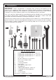
Parts Identification FIG-A FIG-B FIG-C 8
1. Remove all polystyrene packaging material, then, with assistance lift the machine on to a workbench. DO NOT attempt to do this single handedly. 2. Unbolt the machine from the board - 4 nuts with countersunk screws and washers, and, with assistance, carefully slide or lift into position on your workbench. 3. Before drilling the bench in order to secure the machine, ensure : 4.
OPERATION Ensure the work area is clean and tidy and all tools and accessories etc., are removed and stored safely, before plugging the machine into the electric supply. Switch the power ON. At this point, the green indicator lamp on the switch panel on the front of the machine, will illuminate, indicating that power is being supplied to the machine. Fig.2 When first using the machine, please use the following procedure. 1.
In order to hold the spindle, insert the Tommy Bar into the hole in the side of the head so that it locates in the hole in the spindle, see Fig. 5. Hold the spindle still whilst nipping up the draw bolt. . Fig.6 Place the drill chuck on to the end of the taper shank with a sharp upward movement. The drill is lowered using the levers on the right side of the machine, however, in order to do so, it is first of all necessary to disconnect the Dog Clutch, shown in Fig. 6.
17 B. Milling Vertical Milling is similar to drilling, except that instead of the workpiece being held stationary, it may be moved in 3 directions - a. vertically, and b. horizontally in both axis. Milling cutters are capable of cutting with their ends and their faces.
knob whilst grasping the knurled rim of the scale and turning until the zero on the scale lines up with the pointer. Back off slightly and start the machine. Turn the adjuster once again until the zero mark lines up with the pointer and double check that the cutter is just touching the work - if not, make the necessary adjustment. Any further movement of the adjuster will commence cutting. General Notes on Milling Set up the workpiece in a similar manner to that for drilling.
Maintenance The amount of maintenance depends on the amount of use the machine gets. However, it is important to carry out routine maintenance to prevent premature wear and shortening the life of the machine. 1. Inspect and clean all non painted surfaces. Lubricate using a light machine oil. Do Not over lubricate. Oil can be applied to the work table and column etc., using a soft oil soaked cloth. 2. Inspect and clean all moving parts. Lubricate using machine oil. Check for smooth operation. 3.
Parts Diagram 15
Parts Diagram 16
Parts Diagram PARTS & SERVICE TEL: 020 8988 7400 or e-mail as follows: PARTS: Parts@clarkeinternational.com SERVICE: Service@clarkeinternational.
Parts List Item Description Qty Part No Item Description Qty Part No SGCMD300040 1 Base 1 SGCMD300001 40 Spring washer 10 3 2 X-axis feed screw 1 SGCMD300002 40-1 Washer 10 3 SGCMD3000401 2-1 Key 4xl6 2 SGCMD300003 41 Cap screw Ml0 x 30 3 SGCMD300041 4 Dial 2 SGCMD300004 42 Pointer 2 SGCMD300042 5 Hand wheel 2 SGCMD300005 43 Set screw M6 x 22 7 SGCMD300043 6 Nut M8 2 SGCMD300006 44 Scale 1 SGCMD300044 7 Knob 2 SGCMD300007 45 Jib Strip 1 SGCMD30004
Parts List Item Qty Part No 85 Sleeve Description 1 SGCMD300085 Item Description Qty Part No 126 Cover 1 86 Pin 3xl2 I SGCMD300086 127 Motor 1 SGCMD300127 87 Pin 3xl2 2 SGCMD300087 128 Motor gear 1 SGCMD300128 SGCMD300126 88 Adjustable union 1 SGCMD300088 129 Ring 9.
Accessories 1. Mill Chuck Set Part Number: 7610866 A set comprising 7 collets, a chuck and ‘C’spanner. Collet sizes: • 4 mm • 6 mm • 8 mm • 10 mm • 12 mm • 14 mm • 16 mm A 1. Insert the shank of the chuck into the Mill Head Spindle and screw on to the end of the draw bolt. Tighten the draw bolt, holding the spindle steady by hand or by inserting the tommy bar provided in the hole in the side of the head and into the spindle. 2.
3. Collet Set (MT3) Part Number: 7610864 A set of 7 Collets for use with the HSS End Mills: Insert the appropriate Collet into the spindle. Insert the draw bolt, provided, into the spindle, from the top and screw on to the Collet a few turns. Insert the appropriate Mill into the jaws of the Collet, and tighten the draw bolt. Hold the spindle by means of the tommy bar, inserted in the hole in the side of the head, and into the hole in the spindle.
5. Indexable Carbide End Mill Part Number: 7910870 Simply insert the shank of the mill into the spindle and screw on to the Draw Bolt. Tighten using the Tommy Bar in the hole in the side of the head, into the spindle, and spanner on the Draw Bolt head. Disassemble in the same manner as for the drill chuck. 6. Clamp Set Part Number: 7610872 An example of how the clamp set may be used: Select the appropriate studs and slotted clamp.