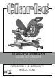
0”SLIDING MITRE SAW MODEL NO: CMS10S2 PART NO: 6461514 OPERATION & MAINTENANCE INSTRUCTIONS LS0312
INTRODUCTION Thank you for purchasing this CLARKE 10”Sliding Mitre Saw. Before attempting to use this product, please read this manual thoroughly and follow the instructions carefully. In doing so you will ensure the safety of yourself and that of others around you, and you can look forward to your purchase giving you long and satisfactory service. IMPORTANT Please read all of the safety and operating instructions carefully before using this product.
TABLE OF CONTENTS INTRODUCTION ..........................................................................2 IMPORTANT ................................................................................2 GUARANTEE ...............................................................................2 TABLE OF CONTENTS ..................................................................3 GENERAL SAFETY RULES .............................................................4 ADDITIONAL SAFETY RULES FOR MITRE SAWS .............
GENERAL SAFETY RULES 5. If operating the power tool in a damp location is unavoidable, use a residual current device (RCD) protected supply. WORK AREA 1. Keep the work area clean and well lit. Cluttered and dark areas invite accidents. PERSONAL SAFETY 2. Do not operate power tools in explosive atmospheres, such as in the presence of flammable liquids, gases or dust. Power tools create sparks which may ignite the dust or fumes. 1.
GENERAL SAFETY RULES and any other condition that may affect the power tools operation. If damaged, have the power tool repaired before use. Many accidents are caused by poorly maintained power tools. 6. Dress properly. Do not wear loose clothing or jewellery. Keep your hair, clothing and gloves away from moving parts. Loose clothes, jewellery or long hair can be caught in moving parts. 6. Keep cutting tools sharp and clean. Tools with sharp cutting edges are less likely to bind and are easier to control.
ADDITIONAL SAFETY RULES FOR MITRE SAWS 15. Keep the surrounding area of the machine well maintained and free of loose materials, e.g. chips and cut-offs. 5. Never attempt to stop a machine in motion rapidly by jamming a tool or other means against the blade; serious accidents can be caused unintentionally in this way. 16. Before use, check that the motor air slots are clean and free of chips. 6. Before using any accessory consult the instruction manual. The improper use of an accessory can cause damage.
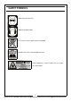
SAFETY SYMBOLS Wear eye protection Wear ear defenders Do not put your hand near the blade Read instruction manual before use Laser Radiation, Class 2 Laser: Do not stare into the beam. 7 Parts & Service: 020 8988 7400 / E-mail: Parts@clarkeinternational.com or Service@clarkeinternational.
ELECTRICAL CONNECTIONS WARNING! Read these electrical safety instructions thoroughly before connecting the product to the mains supply. Before switching the product on, make sure that the voltage of your electricity supply is the same as that indicated on the rating plate. This product is designed to operate on 230VAC 50Hz. Connecting it to any other power source may cause damage. This product may be fitted with a non-rewireable plug.
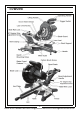
OVERVIEW 9 Parts & Service: 020 8988 7400 / E-mail: Parts@clarkeinternational.com or Service@clarkeinternational.
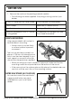
BEFORE USE 1. Remove the saw from the packing material carefully. • The following should be supplied. If anything is missing contact your dealer. Cross-Cut Mitre Saw with Laser Guide 2 AAA Batteries (for laser guide) Work Clamp Spare Pair of Carbon Brushes 2 x Work Supports Shavings / Dust Collection Bag 254 mm Diameter 60 Tooth TCT Wood Cutting Blade Combined 6 mm Hexagon Key and Cross Head Screwdriver BENCH MOUNTING Holes are provided in all four feet to facilitate bench mounting.
LOCKING / RELEASING THE SAW HEAD 1. Press down slightly on the operating handle and pull out the Head Lock Pin, and rotate it 90 degrees as shown. 2. Gently release the downward pressure on the operating handle and allow the head to rise to its full height. FITTING THE WORK CLAMP 1. Loosen the thumb screw on either of the clamp supports. 2. Slide the work clamp into the clamp supports. 3. Tighten the thumb screw to secure the work clamp.
FITTING WORK SUPPORTS 1. Loosen the work support securing screw. 2. Slide the work supports into place as shown. 3. Secure them in place by tightening the work support securing screw. DUST EXTRACTION This machine is provided with a dust extraction point for connection to a dust bag (supplied). 1. Place the dust bag over the dust extraction port using the clip on the neck of the dust bag. 2. Make sure the zipper on the dust bag is closed. 3.
INSTRUCTIONS FOR USE Always observe the safety instructions and applicable regulations. BODY AND HAND POSITION Proper positioning of your body and hands when operating the mitre saw will make cutting easier and safer. • Never place your hands near the cutting area or blade. • Hold the workpiece tightly to the table and the fence when cutting. • Keep your hands in position until the trigger switch has been released and the blade has completely stopped.
BASIC SAW CUTS VERTICAL STRAIGHT CROSS CUT 1. Release the table mitre lock and move the arm to the 0° position and re-tighten the table mitre lock. 2. Release the slide rail lock, and push the saw head back to the rear position. 3. Retighten the slide rail lock. 4. Place the wood to be cut against the fence. 5. Take hold of the operating handle and press and hold the blade guard release lever (1) to release the head. 6. Squeeze the trigger switch (2) to start the saw. 7.
PERFORMING A SLIDING CUT The guide rail allows cutting larger workpieces up to 340 mm x 78 mm using an out-down-back sliding motion. 1. Release the slide rail lock. 2. Pull the saw head towards you (1) and switch the saw on as mentioned on the previous page. 3. Lower the saw blade (2) into the workpiece and push the head back (3) to complete the cut. • Do not perform sliding cuts on workpieces smaller than 50 x 100 mm. • Remember to lock the saw head in the rear position when the sliding cuts are finished.
BEVEL CUTS Bevel angles can be set from 45° left to vertical and can be cut with the mitre arm set between zero and a maximum of 45° mitre position right or left. 1. Loosen the bevel adjustment handle and set the bevel at the desired angle. 2. Tighten the bevel adjustment handle firmly. 3. Proceed as for a vertical straight cross-cut. • Allow the blade to cut freely. Do not force the tool. MITRE / BEVEL CUTS As the number of sides changes, so do the mitre and bevel angles.
GROOVE CUTTING Your saw is equipped with a grooving stop and thumbscrew to allow for groove cutting. 1. Firstly, determine the depth of your groove, and subtract this value from the thickness of your workpiece. This will give you the height above the table surface at which the saw blade must be set. 2. Ideally, place a template or a piece of wood, the same thickness as the saw blade height setting, on the table, beneath the saw blade. 3. Pivot the groove plate to the side position shown. 4.
TRANSPORTING 1. Lower the head and lock it down using the head lock pin. 2. Slide the head towards you and secure in place using the slide rail lock. 3. Lock the mitre arm with the table mitre lock. 4. Lock the bevel adjustment handle with the saw head in the vertical position to make the tool as compact as possible. 5. Always lift the saw using the lifting handle. THE LASER GUIDE Your saw is fitted with a laser guide to assist with accurate cutting. INSERTING THE BATTERIES 1. Remove the battery cover. 2.
ADJUSTMENTS WARNING: MAKE SURE THAT THE SAW IS SWITCHED OFF AND UNPLUGGED FROM THE MAINS SUPPLY BEFORE PERFORMING ANY ADJUSTMENTS. CHECKING AND ADJUSTING THE MITRE SETTINGS 1. Release the blade guard release lever to release the mitre arm. 2. Lower the head until the blade just enters the kerf plate. 3. Place a set square against the left side of the fence and blade. Move the mitre arm if required until the blade is perfectly square to the fence. 4.
CHECKING AND ADJUSTING THE BEVEL SETTINGS 1. Loosen the bevel clamp handle. 2. Press the saw head to the right to ensure it is fully vertical and tighten the bevel clamp handle. 3. Pull down the head until the blade just enters the kerf plate. 90 DEGREE STOP ADJUSTMENT 4. Place a set square on the table and up against the blade. NOTE: Do not touch the tips of the blade teeth with the square. If adjustment is required, proceed as follows: 5.
45 DEGREE STOP ADJUSTMENT 1. Loosen the bevel clamp handle and set the saw head as far to the left as possible (this should be the 45° angle) 2. Place a 45° set square on the table and up against the blade. NOTE: Do not touch the tips of the blade teeth with the square. 3. Turn the 45° adjustment stop screw in or out until the blade is at 45° to the table as measured with the square. 4. Adjust the bevel point if required as shown in point 6 above.
MAINTENANCE WARNING: MAKE SURE THAT THE SAW IS SWITCHED OFF AND UNPLUGGED FROM THE MAINS SUPPLY BEFORE FITTING OR REMOVING THE BLADE. WARNING: THE BLADE MUST BE RATED TO AT LEAST 6000 RPM. CHANGING THE SAW BLADE Install the appropriate saw blade. Do not use excessively worn blades. The maximum rotation speed of the tool must not exceed that of the saw blade. 1.
CHANGING THE CARBON BRUSHES WARNING: MAKE SURE THAT THE SAW IS SWITCHED OFF AND UNPLUGGED FROM THE MAINS SUPPLY BEFORE CHANGING THE CARBON BRUSHES. A spare pair of carbon brushes are supplied with the machine. Should it become necessary to change these: 1. Unscrew the brush holder plug. 2. Pull out the worn brushes. 3. Replace with new brushes. 4. Replace the brush holder plug, taking care not to cross thread it.
SPECIFICATIONS Model Number CMS10S2 Part Number 6461514 Rated Voltage 230 V @ 50Hz Input Wattage 1800 W Blade Diameter 254 mm Blade bore 30 mm Max. blade thickness 2.8 mm Max. blade speed 6000 RPM. Max. crosscut capacity at 90° 340 mm x 78 mm Max. mitre cut capacity at 45° 240 mm v 78 mm Max. bevel cross-cut 45° 340 mm x 42 mm Max. Compound Mitre Cut 240 mm x 42 mm Max Bevel Angle 45° to the left Sound pressure (LpA) 91.9 dB (A) Sound power (LWA) 104.
EXPLODED DIAGRAM 25 Parts & Service: 020 8988 7400 / E-mail: Parts@clarkeinternational.com or Service@clarkeinternational.
PARTS LIST Part No No Description Main Frame WSCMS10S202 101 Spring WSCMS10S2101 Rubber Foot WSCMS10S203 103 Washer WSCMS10S2103 Workpiece Support WSCMS10S207 107 Cover WSCMS10S2107 Handle WSCMS10S210 109 Guard Locking Lever WSCMS10S2109 14 Pointer WSCMS10S214 111 Spring WSCMS10S2111 15 Table WSCMS10S215 116 Bearing WSCMS10S2116 21 Table Insert + Kerf Plate WSCMS10S221 122 Anchor WSCMS10S2122 125 Stator WSCMS10S2125 22 Shim WSCMS10S222 128 Carbon Brush Holder
DECLARATION OF CONFORMITY 27 Parts & Service: 020 8988 7400 / E-mail: Parts@clarkeinternational.com or Service@clarkeinternational.