COMPOUND MITRE SAW Model CMS251 OPERATION & MAINTENANCE © INSTRUCTIONS 0801
© Copyright Clarke International.
Thank you for purchasing this CLARKE 10 inch Compound Mitre Saw. This extremely versatile machine is designed for DIY/Hobby use and for use by tradesmen in a light industrial environment Before operating the machine, please read this leaflet thoroughly and carefully follow all instructions. This will ensure the safety of yourself and that of others around you, and you can also look forward to the machine giving you long and satisfactory service.
GENERAL SAFETY RULES FOR OPERATING MACHINERY WARNING: As with all machinery, there are certain hazards involved with their operation and use. Exercising respect and caution will considerably lessen the risk of personal injury. However, if normal safety precautions are overlooked or ignored, personal injury to the operator or damage to property, may result. 1. READ and BECOME FAMILIAR with the entire operating manual.
11. REMOVE ADJUSTING KEYS AND WRENCHES. Form the habit of checking to see that keys and adjusting wrenches are removed from the machine before switching on. 12. Do not operate machine while under the influence of DRUGS, ALCOHOL OR ANY MEDICATION. 13. USE ONLY RECOMMENDED ACCESSORIES. The use of improper accessories could be hazardous. 14. NEVER LEAVE MACHINE RUNNING UNATTENDED. Turn power OFF. Do not leave machine until it comes to a complete stop. 15.
ADDITIONAL SAFETY INSTRUCTIONS for MITRE SAWS 1. Wear safety goggles as protection against flying wood chips and saw dust. In many cases, a full face shield is even better protection. A dust mask is also recommended to keep saw dust out of your lungs. 2. Use a solid wood workbench which will not move under load. 3. This saw is designed for use by DIY/Hobbyists, or tradesmen in a light commercial environment ONLY. 4. Clear the work table of all objects except the workpiece (tools, scraps, rulers etc.
ELECTRICAL CONNECTIONS Connect the mains lead to a standard, 230 Volt (50Hz) electrical supply through an approved 13 amp BS 1363 plug, or a suitably fused isolator switch.
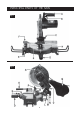
PRINCIPAL PARTS OF THE SAW Fig.1 Fig.
LEGEND A Cutting Head Release Lever J Table Release Lever B K Pointer C Cutting Head Locking Pin L Stabiliser D Table Locking Knob M Bevel Scale E Work Clamp N Bevel Locking Knob F Back Fence O Head Return Spring Tension Adjuster Trigger Switch (ON/OFF) G Table Insert P H Front Mounting Hole Q Dust Bag Cutting Head Stop Screw FEATURES (Ref. Figs.
ASSEMBLY and INSTALLATION. Re: Figs 1 & 2 On receipt inspect the machine to ensure that all parts are accounted for and that no damage was incurred during transit. Any deficiency or damage should be reported to your CLARKE dealer immediately. The main body of the saw is fully assembled and adjusted at the factory. It is necessary only to fit the accessories supplied as follows: Fig.3 1. 2. 3. 4. 5. 6. 7. Mount the machine on a firm solid base that will not move under load.
OPERATION. A. Cross Cutting (at 90O) Ref: Figs 1 & 2 First, set the work in place. Clamp it firmly against the table and back fence. Check the security of the Bevel Locking Knob (N) and tighten if necessary, also ensure the table is locked using the Table Locking Knob (D). NOTE: If the workpiece is not entirely straight, ensure that the portion at either side of the intended cut rests firmly against the table and back fence.
C. Straight Bevel Cutting As with Mitre Cutting, this is a cross cutting operation, except that the blade is not perpendicular to the table (see illustration) Fig.6 Ensure the table is set so that the table pointer lines up with the zero on the scale on the bed. Slacken off the Bevel Locking Knob (N), and swing the Head to the side. Set the head to the required angle according to the scale (M). Lock the head in position by retightening the Bevel Locking Knob.
MAINTENANCE 1. General User maintenance is limited to changing the saw blade when necessary, renewing the motors’ carbon brushes, maintaining adjustments, and ensuring that after use, any sawdust or wood chips are cleaned away, with a low pressure air line or brush, paying particular attention to the motor air vents which should be kept clear at all times.
Fig.11 4. Remove the screw securing the upper plastic guard, arrowed in Fig.11, and pull away the guard. 5. Unscrew and remove the Blade securing screw using the claw and box spanners provided, taking great care to avoid damaging your hand on the saw blade teeth. Fig.12 IMPORTANT: The securing screw has a LEFT HAND THREAD, i.e. turn it CLOCKWISE to undo. Fig.13 6. Remove the outer flange followed by the blade. If necessary give the blade a gentle tap to dislodge it from the inner flange. 7.
3. Renewing Motor Brushes Eventually, the motors’ carbon brushes will need replacing. This task may be carried out quickly and easily as follows. 1. Remove the two cross head screws, securing the motors’ end cover, and pull off the cover. 2. Disconnect the spade connector, shown in Fig. 15, then pull out the brush carrier, complete with brush, as shown in Fig. 14. Fig.14 The cable is located on a plastic peg, shown in Fig. 15 and will simply pull away as you remove the brush. 4.
ADJUSTMENTS Ref: Fig 16 It may be necessary from time to time, to check various settings and make appropriate adjustments. a. Squareness of Blade It is most important to check that the blade is exactly perpendicular to the table. To do this, place a small square on Fig.16 the table and bring it up to the blade, checking to see if it is square.
SPECIFICATIONS Motor: ................................................................... 230V 50Hz 1phase. Running Current ........................................ 6.5Amps Power Rating: ............................................ 1400 Watts Speed: ....................................................... 3900RPM Fuse Rating .............................................................. 13Amps Dimensions: (Head Lowered) ................................ 445x490x365mm Dimensions: (Head Raised) ..............
PARTS LIST No.
PARTS DIAGRAM 19