5 DEGREE COIL NAILER Model CON15 Part No: 3110295 OPERATING & MAINTENANCE INSTRUCTIONS GC0309
INTRODUCTION Thank you for purchasing this CLARKE Coil Nailer Before attempting to operate the machine, it is essential that you read this manual thoroughly and carefully follow all instructions given. In doing so you will ensure the safety of yourself and that of others around you, and you can also look forward to the product giving you long and satisfactory service. GUARANTEE This CLARKE product is guaranteed against faulty manufacture for a period of 12 months from the date of purchase.
OVERVIEW The CON15 Coil Nailer is suitable for use on softwood, hardwood, plywood, hardboard, fibreboard or MDF, and will penetrate flexible plastics, leather, fabrics, PVC & rubber sheet materials. It is not suitable for piercing hard laminates, brittle plastics or metals (other than light foil). Unpack and lay out the components, checking against the following list. Any damage or deficiency should be reported to your Clarke dealer immediately.
9 5 6 7 4 3 2 1 8 1. Nail Magazine 2. Drive Pawl 3. Protective Screen 4. Safety Yoke (muzzle) 5. Mode Switch (single/full contact sequential actuation) 6. Trigger 7. Pressure Adjuster 8. Compressed Air Hose Connector 9.
GENERAL SAFETY PRECAUTIONS WORK AREA 1. ALWAYS Keep the work area clean and well lit. Floors should always be kept clear. Cluttered or dark areas invite accidents. 2. ALWAYS keep children and bystanders away while operating a power tool. Distractions can cause loss of control. PERSONAL SAFETY 1. ALWAYS stay alert, watch what you are doing and use common sense when operating a power tool. Do not use a power tool while you are tired or under the influence of medication, drugs or alcohol.
. ALWAYS disconnect the tool from the air supply when not in use, and before carrying out any maintenance or re-loading with fresh nails. 7. ALWAYS Store the tool out of reach of children. 8. NEVER allow persons unfamiliar with these instructions to operate this tool. SERVICING 1. ALWAYS have power tools serviced by your Clarke dealer, using only identical replacement parts. This will ensure the safety of the power tool is maintained. COIL NAILER SAFETY INSTRUCTIONS 1.
THE COMPRESSED AIR SUPPLY WARNING: COMPRESSED AIR CAN BE DANGEROUS. ENSURE THAT YOU ARE THOROUGHLY FAMILIAR WITH SAFETY PROCEDURES RELATING TO THE USE OF COMPRESSORS AND COMPRESSED AIR SUPPLIES. A filtered, lubricated and regulated air supply will be required as shown in the layout below. Ensure the pressure available is within the range of 70-100 psi. Higher pressure or contaminated air will shorten the tool’s life because of increased wear, and could be a safety hazard.
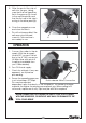
LOADING THE COIL NAILER WARNING: ENSURE THE COMPRESSED AIR SUPPLY IS DISCONNECTED BEFORE ATTEMPTING TO LOAD THE COIL NAILER. DO NOT HOLD THE TRIGGER WHILE LOADING THE NAILER. The machine is loaded with nails as follows: 1. Press the latch (1) open and pull the magazine cover (2) back. 2. Knowing the nail size to be used, raise and twist the adjuster 90 degrees for the chosen nail size as required. 3.
5. Offer the end of the strip of nails into the gun, taking care that the nail heads lay flat in the groove (5) closest to the machine body and that the first nail in the strip is resting in the drive pawl (6). 6. Close the magazine cover and close the latch. • This will not be possible if the nails are not positioned correctly. The machine is now ready to use. 6 5 OPERATION 1. Connect the nailer to the air supply. With the air supply turned OFF, connect the air line to the ¼” BSP connector.
4. Before starting work, test the nailer on a piece of scrap wood to check that the driving depth is correct. If the nails are being driven too far or not deep enough into the timber, adjust the air pressure adjuster located on the side of the nose section accordingly. (Remember; whatever pressure adjustment is to be carried out on the tool is dependant upon the pressure received from the airline). Pressure adjuster 5. Hold the tool so that it is at right angles to the workpiece.
MAINTENANCE WARNING: ENSURE THE COMPRESSED AIR SUPPLY IS DISCONNECTED BEFORE ATTEMPTING ANY MAINTENANCE ON THE COIL NAILER. DAILY BEFORE USE 1. Check and clean, if necessary, the air inlet gauze filter located inside the air hose connection point. 2. A bottle of Clarke airline oil is supplied with the Coil Nailer. Unscrew the cap & withdraw the nozzle which is reversed within the neck of the bottle. Screw the cap and nozzle correctly into place and squirt a few drops of oil, into the air inlet.
Grit or gum deposits in the tool may also reduce efficiency. This condition can be corrected by cleaning the air strainer and flushing out the tool with gum solvent oil, or failing this, the tool should be dismantled, thoroughly cleaned, dried and reassembled. This is a task for your Clarke dealer.
TROUBLESHOOTING SYMPTOM Air leak near top of tool or in the trigger area. PROBLEM SOLUTION 1. O-ring in trigger valve area damaged. 1. Examine & replace O-ring 2. Trigger valve head is damaged. 3. Trigger valve stem, seal or O-ring are damaged. 2. Examine & replace. 3. Examine and replace trigger valve stem, seal or O-ring. 1. T ighten screws Air leak near bottom of 1. Loose screws. tool. 2. Worn or damaged O-ring 2. Examine & replace O-ring or bumper. or bumper. Air leak between body 1.
PARTS LIST No Description No Description Part No Part No 1 Bolt HTCON15001 26 Valve O - Ring HTCON15026 2 Air Deflector HTCON15002 27 O - Ring HTCON15027 3 Spring Plate HTCON15003 28 Valve Sleeve HTCON15028 4 Cylinder Bolt HTCON15004 29 O - Ring HTCON15029 5 Hex Bolt HTCON15005 30 O - Ring HTCON15030 6 Gun Body Protector HTCON15006 31 O - Ring HTCON15031 7 Cylinder Cover HTCON15007 32 Trigger Spring HTCON15032 8 Hex Headed Bolt HTCON15008 33 Trigger Pole HTCON15033
PARTS LIST No Description Part No No Description Part No 51 Adjusting Bolt HTCON15051 76 Magazine HTCON15076 52 Compression Spring HTCON15052 77 Magazine Cover HTCON15077 53 Adjusting Bolt HTCON15053 78 Anvil HTCON15078 54 Hex Bolt HTCON15054 79 2-Spring Hook HTCON15079 55 Pawl HTCON15055 80 Adjusting Plate HTCON15080 56 Pawl Spring HTCON15056 81 Aluminium Plate HTCON15081 57 P i n HTCON15057 82 Adjusting Sleeve HTCON15082 58 3 - P i n HTCON15058 83 Nail Depth Adjusting Bas
PARTS DIAGRAM 16
VIBRATION EMISSIONS HAND-ARM VIBRATION Employers are advised to refer to the HSE publication “Guide for Employers”. All hand held power tools vibrate to some extent, and this vibration is transmitted to the operator via the handle, or hand used to steady the tool. Vibration from about 2 to 1500 herz is potentially damaging and is most hazardous in the range from about 5 to 20 herz.
You will note that a third value is given in the specification - the highest measured reading in a single plane. This is the maximum level of vibration measured during testing in one of the axes, and this should also be taken into account when making a risk assessment. ‘a’ values in excess of 2.5 m/s2 are considered hazardous when used for prolonged periods. A tool with a vibration value of 2.8 m/s2 may be used for up to 8 hours (cumulative) per day, whereas a tool with a value of 11.
DECLARATION OF CONFORMITY 19