
Technical data


21
© Baxi Heating UK Ltd 2006
Installation Instructions
Compact Heat Pump Installation Instructions
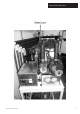
1. Decide on a suitable location for the Compact. The back of a domestic garage, or a utility room is recommended. It should not be placed in any inhabited
space. The Compact emits limited noise and vibration, and should not be placed adjacent to, or below bedrooms. Take into account the “Recommended
Clearances” when finalising the location.
2. Remove the door by turning the lock with a screwdriver, opening and lifting off.
3. Remove the hood by unscrewing the 5 mm hex key screws on either side of the base of the hood. Carefully lift the hood off, which may require two people.
4. Remove all three lower closure panels necessary to gain access to the pipe connections, by unscrewing the 4 x hex-headed stainless steel screws on each
panel.
5. Place the Compact in position and level it using the adjustable feet if necessary. Tighten the locking nuts on the feet when level.
6. Ensure the underfloor heating system has been thoroughly purged of any debris.
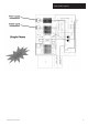
7. Using only plastic flexible pipe such as Speedfit
®
connect the cold feed, ground feed & return pipes from the Slinky
®
Manifold (which can be connected either
way round), feed & return pipes from the underfloor heating manifold (which must be connected the correct way round), according to the Plumbing
Connections Illustration. Flexible pipe must be used as the heat pump is suspended on anti-vibration mounts, so any connections must also be flexible.
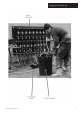
8. Thread the power supply and timeclock/room thermostat wires from under the Compact into the control box and connect them to the terminals required
(see "wiring connections" illustration).
9. Fit the weather compensation sensor on a North facing wall, and connect with two-core minimum 0.5mm sq cable to the connections in the control box (see
"wiring connections" illustration). The wires can be connected either way round. Avoid routing this cable with any other cables to prevent interference.
10. Check and rectify any leaks that may be in the plumbing system.
11. Remove the plastic blanking plugs, and connect the purge pump to the fill and purge ports on the Slinky
®
Manifold (see "Purging the ground arrays"). Keep the
isolating valve to the heat pump closed. The purge ports can be connected either way round.
12. Connect the purge pump to suck from an 80 litre container (such as a dustbin) half filled with clean water. The pump must be capable of moving around 60
litres per minute against a pressure of approximately 1 bar. If the pump’s electrical rating is less than 1 kW, then it is unlikely to be suitable. The water level in the
container will need to be topped up constantly during the following process. The pump may need priming by pouring water into its priming port until it
overflows. Open the flow and return valves to one slinky
®
, and ensure that the others are closed, and the valve to the heat pump is also closed. Open the fill and
purge port valves (see "Purging the ground arrays").
13. Place a filter such as a kitchen sieve over the end of the pipe that returns water to the container so any debris will be captured. Start the purge pump, being
careful that the pipe returning water to the container does not splash or whip round and cause any injury.
14. Water should now be being pumped from the 80 litre container and into one of the slinkies
®
. If the water level in the container does not go down, then
pump priming should be repeated. No water should be flowing through the heat pump or through the other slinky
®
. The flow rate should be significant, usually in
excess of 30 litres per minute. This can easily be checked by holding a 10 litre bucket to collect water returning from the slinky
®
, and ensuring that it fills the
bucket in less than 20 seconds. If the flow is less than this sufficient velocity for the air in the tops of the slinkies
®
to be displaced is not being achieved. Purge each
slinky
®
for at least 10 minutes.