BELT/DISC SANDER MODEL NO: CS4-6C PART No: 6500401 OPERATION & MAINTENANCE INSTRUCTIONS 0607
CONTENTS Specifications......................................................................................3 Safety Precautions..............................................................................4 Electrical Connections.......................................................................6 Pre-Assembly Check..........................................................................7 Assembly Instructions..........................................................................
Thank you for purchasing this CLARKE Belt and Disk Sander designed for hobby/ DIY, indoor use, and for sanding wood or wood products ONLY. Before attempting to use the sander, please read this manual thoroughly and follow the instructions carefully. In doing so you will ensure the safety of yourself and that of others around you, and you can look forward to the sander giving you long and satisfactory service. These instructions should be retained and used for reference by all those who use the equipment.
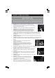
SAFETY PRECAUTIONS WARNING: As with all machinery, there are certain hazards involved with their operation and use. Exercising respect and caution will considerably lessen the risk of personal injury. However, if normal safety precautions are overlooked or ignored, personal injury to the operator or damage to property, may result. 1. ALWAYS Learn the machines applications, limitations and the specific potential hazards peculiar to it. Read and become familiar with the entire operating manual. 2.
14. ALWAYS wear proper apparel. Loose clothing or jewellery may get caught in moving parts. Wear protective hair covering to contain long hair. 15. ALWAYS guard against electric shock. Avoid contact with earthed surfaces..pipes, radiators etc. 16. NEVER operate machine while under the influence of drugs, alcohol or any medication. 17. NEVER leave machine running unattended. Turn power off. Do not leave the machine until it comes to a complete stop. 18.
ELECTRICAL CONNECTIONS Connect the mains lead to a standard, 230 volt (50Hz) electrical supply through a fused good quality 13 amp BS 1363 plug, or a suitable fused isolator switch.
PRE-ASSEMBLY CHECK Separate all parts from packing materials and check each item with the “Table of Loose Parts.” Make certain all items are accounted for, before discarding any packing material. WARNING: If any parts are missing, do not attempt to assemble the Belt and Disc Sander, plug in the mains lead, or switch until the missing parts are obtained and Installed correctly.
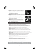
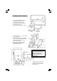
ASSEMBLY Tools Required Mounting To Workbench If Belt and Disc Sander is to be used in a permanent location, it should be fastened securely to a firm supporting surface such as a workbench. If mounting to a workbench, holes should be drilled through supporting surface of the workbench using dimensions illustrated. 1. The unit should be bolted securely using 5/16" screws, flat washers and hex nuts (not included). Screw length should be 1½" plus the thickness of the bench top. 2.
Clamping To Workbench The belt and disc sander can be clamped directly to the board using two or more “G” clamps on base of unit (one clamp on each end). Installing Sanding Disc And Guard 1. Locate sanding disc and peel backing from disc. Align perimeter of disc with plate and press disc firmly into position all the way around. 2. Locate disc guard and two M4 pan head screws, from loose parts bag. 3. Position disc guard against lower 1/3 of disc aligning holes as shown. 4.
Installing Table Assembly 1. Locate table support and (3) M6 hex head screws, flat washers and lockwashers among loose parts. 2. Position table support against table, aligning holes as shown. 3. Fasten table support to table as shown. 4. Locate washer 6.5 x 17.8 x 1.6 and knob among loose parts. 5. Position table support in corresponding holes on side of base as shown. Make sure the 9.5mm diameter index pin aligns with upper hole. 6.
Auxiliary Mounting For Vertical Sanding 1. Remove backstop lock bolt and remove work support. 2. Remove table assembly by removing table lock knob and washer. NOTE: Belt bed may be raised to vertical position by loosening hex socket screw and raising bed. See “Positioning Belt Bed” on page 16. 3. Attach table assembly to auxiliary holes in belt bed. Make sure index pin is in the upper hole when sanding table is in the vertical position.
3. Slide tension lever to the left to apply belt tension. 4. Tighten hex socket screw when bed is in desired position. 5. Plug in the power cord. Turn switch “ON” and immediately “OFF,” noting if the belt tends to slide off the idler pulley or drive pulley. If it did not tend to slide off, it is TRACKING properly. 6. If the sanding belt moves toward the disc, turn the tracking knob clockwise 1/4 turn. 7. If the sanding belt moves away from the disc, turn the tracking knob anticlockwise 1/4 turn. 8.
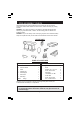
GETTING TO KNOW YOUR BELT/DISC SANDER WARNING: To avoid injury from accidental start, switch “OFF” and disconnect from power source before making any adjustments. 1. Work Support. Supports the workpiece on the sanding belt. 2. Hex Socket Head Screw. Loosening screw allows belt bed to be raised to the vertical position. 3. Tracking Knob. Turning knob anticlockwise causes sanding belt to move towards the disc; turning knob clockwise causes sanding belt to move away from the disc. 4. Tension Lever.
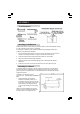
ON-OFF Switch The ON/OFF switch has a locking feature. This feature is intended to help prevent unauthorised and possibly hazardous use by children and others. 1. To turn machine “ON’ insert key into switch. NOTE: Key is made of yellow plastic, located in loose parts bag . 2. Insert finger under switch lever and PULL end of switch out. 3. To turn machine “OFF”... PUSH lever in. NEVER LEAVE THE MACHINE UNATTENDED UNTIL IT COMES TO A COMPLETE STOP. 4. To lock switch in OFF position..
OPERATING INSTRUCTIONS Bevel Sanding The worktable can be tilted from 00 to 450 for bevel sanding. Loosen the table lock knob and tilt the work-table to desired angle as shown. Retighten table lock knob. WARNING: To avoid trapping the work or fingers between the table and sanding surface, the table should be repositioned on the table support to retain a maximum of 1/16 Inch distance between sanding surface and table.
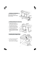
Surface Sanding On The Sanding Belt WARNING: To avoid injury from slips, jams or thrown pieces, adjust the backstop to clear the sanding surface by no more than 1/16”. When checking clearance between the belt and work support, press the belt flat against the bed beneath it. Hold the workpiece firmly with both hands, keeping fingers away from the sanding belt. Keep the end up against the backstop and move the work evenly across the sanding belt. Use extra caution when sanding very thin pieces.
Always sand outside curves on the left side of centre on the sanding disc as shown. WARNING: Applying the workpiece to the right side of the disc could cause workpiece to fly up (kick-back) and result In an Injury. Sanding Small End Surfaces On The Sanding Disc NOTE: Use of a Mitre Gauge is recommended for this operation. Always move the work across left side of centre on the sanding disc face as shown. The table may be tilted for bevelled work.
MAINTENANCE WARNING: For your own safety, switch “OFF” and remove plug from power source before adjusting, maintaining, or lubricating your belt and disc sander. WARNING: To avoid electrocution or fire, any repairs to electrical systems should be done only by qualified service technicians. The unit must be reassembled exactly to factory specifications. If the mains lead is worn or cut, or damaged in any way, have it replaced immediately.
4. Slightly tighten (3) screws. Adjust tension of belt by putting blade screwdriver in adjusting hole. Push up on screwdriver to tighten tension between pulleys. 5. Tighten screws fully, being careful not to disturb the belt. 6. Test belt tension by placing fingers on either side of belt and squeeze. There should be about a 1/4" give to the belt. NOTE: Excessive tightness on pulley belt may cause increased noise and over load motor. Excessive looseness on pulley belt may cause belt to fail prematurely. 7.
PARTS DIAGRAM 20
PARTS LIST WARNING: The use of spare parts, other that those supplied by CLARKE International or one of its recognised dealers, may be hazardous and could invalidate the guarantee. Item Description Part No 1 Knob UT820247 2 Washer, Rubber UT820175 3 Washer, Shakeproof UT821156 4 Bed UT8I9496 5 Screw, Flat Cross M5 x 0.8-35 UT820235 6 Screw, Hex M6 x 1.0-12 UT820249 7 Lockwasher, Ext. M6 UT852006 8 Washer, 6.5 x 17.8 x 1.
cont. PARTS LIST Item Description Part No 35 Table UT819487 36 Support, Table UT819490 37 Label, Scale UT819459 38 Cord W/Plug UTB19463 39 Motor (1/3 HP) UT821587 40 Connector, Wire UT375007 41 Nut, Hex M6 x 1.0 UT840610 42 Base UT8I9498 43 Belt, Drive UT8I40023 44 Screw Flat M5 UT8202352 45 Washer, Countersunk UT821586 46 Drive Pulley UT8215851 47 Screw, Pan Hd. M6 x 1.0-2.5 UT8202441 48 Washer, M6 x 12 x 1.
Please note that the details and specifications contained herein, are correct at the time of going to print. However, CLARKE International reserve the right to change specifications at any time without prior notice. CLARKE International.