BELT & DISC SANDER MODEL No. CS6-9C Part No.
-2-
Thank you for purchasing this CLARKE Belt and Disc Sander, which is designed for workshop use and comprises a 9” dia. sanding disc and a 6” wide sanding belt. This machine is designed for sanding WOOD ONLY. DO NOT USE for sanding asbestos, or materials containing asbestos, painted surfaces, or materials which produce toxic dust. Do not use for sanding magnesium as this produces a highly flammable dust.
GENERAL SAFETY RULES 1. ALWAYS KEEP GUARDS IN PLACE and check they are not damaged. 2. ALWAYS REMOVE ADJUSTING KEYS AND WRENCHES. Make a habit of checking to see that all adjusting keys and wrenches are removed from machine before turning it on. 9. ALWAYS DISCONNECT FROM THE MAINS before attempting any kind of service work or adjustment or when changing accessories such as grinding wheels. 10. ALWAYS MAINTAIN TOOLS WITH CARE. Keep tools sharp and clean for best and safest performance. 3.
ELECTRICAL CONNECTIONS Connect the mains lead to a standard, 230 volt (50Hz) electrical supply through a fused good quality 13 amp BS 1363 plug, or a suitable fused isolator switch.
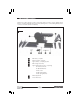
PRE-ASSEMBLY CHECK Unpack the carton and lay out the components and loose items. Check against the list below to ensure that all parts are present. If any damage has occurred during transit, please contact your Clarke dealer immediately. Fig.1 1.
ASSEMBLY 1. Assemble the stand in the manner shown in Fig.2. The four top panels are secured with a single bolt, with flat washer, in each corner, and the legs are then bolted on, followed by the leg braces. Do not tighten the nuts until all bolts are in place and the stand is rocked vigorously to ensure it is stable. When satisfied, tighten securely. Fig.2 2. WITH ASSISTANCE, considering its weight, raise the machine and place it on top of the stand.
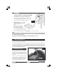
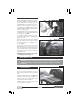
With the belt raised, ensure that nothing can interfere with the disc or belt, and that the Belt Tensioning Lever (1, Fig.4), is pushed fully to the rear - in the direction of the arrow. Fig. 4 Plug in to the mains supply and press the GREEN ON button, marked ‘I’ to start the machine. keeping well away from the belt. Observe the belt as it passes over the front (top) roller....there should be no creep to one side. If it does creep, switch OFF by pressing the RED OFF button, marked ‘O’.
B...to the Belt Fig. 6 Before attempting to attach the table to the belt mounting, raise the belt arm and secure with the two securing screws, as explained under ‘Checks Before Use’, p7. Slide the Table Support bar into the mounting as shown in fig. 6 with the shorter flat on the end of the bar - inwards. Tighten the two securing screws. Mount the table on the support bar, bring to within 2mm of the belt and tighten the securing screws (1, fig 6).
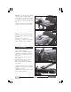
Fig. 8A shows the table being used in conjunction with the Mitre Gauge. Fig. 8A Set the gauge to the angle you require and hold the workpiece firmly against the gauge, feeding it gently into the disc. Keep the workpiece in contact with the left side of the disc as far as possible. Fig. 8B Fig. 8B shows the table set to an angle. The mitre gauge may also be used with this setup. Angles up to 45o may be set. If accuracy is required, check angle using a suitable square or template. B. Using the Belt Fig.
Fig. 9A Curves may be sanded as shown in Fig. 9A Fig. 9B ...or the belt used in the vertical position as shown in Fig.9B. NOTE: The work stop has been removed. DUST EXTRACTION Fig. 10 Provision is made for forced dust extraction on both the disc AND belt. The dust extraction outlets are shown in Fig.10 and have an outside diameter of 56mm (21/4”). Connect a suitable hose to a vacuum cleaner via a reducer, or Dust Extraction device (see your Clarke dealer).
MAINTENANCE CAUTION: Before carrying out any maintenance or servicing, ALWAYS ensure the plug is disconnected from the mains supply. A. Changing the Belt 1. Raise the table and secure in the vertical position. Fig. 11 2. Remove the lower Belt Cover, by slackening the four securing screws sufficiently for the cover to be slipped off. 3. Remove the screw securing the dust hand (or rear) mounting. 4. Slide the Belt Tension Lever fully FORWARD. (As the Belt Arm is vertical, this would be - UPWARDS).
ACCESSORIES Replacement Discs and Belts are available in packs of 5 from your local dealer. Please quote the part numbers below. A. 6” Replacement Belts (150 x 1219mm) Grit size Part No. Fine ..................................................... 6502098 Medium .............................................. 6501164 Coarse ............................................... 6502103 B. 9” Replacement Discs (230mm) Grit size Part No. Fine ..................................................... 6502099 Medium ..
PARTS LIST No. Description Part No.
PARTS DIAGRAM - 15 -