600W ELECTRIC TILE CUTTER MODEL No: ETC400 Part No: 3400748 OPERATION & MAINTENANCE INSTRUCTIONS 0706
SPECIFICATIONS Motor: .......................................................................... 230v ~ 50Hz 1ph Power Rating: ............................................................................... 600W No Load Speed: .................................................................... 3000 RPM Operating Temperature: ............................................... -15°C to 40°C Fuse Rating: .............................................................................. 13 amp Table Dimensions: .....
Thank you for purchasing this CLARKE Tile Cutter designed for DIY and light commercial use for cutting all types of ceramic tiles.. Before attempting to use the cutter, please read this manual thoroughly and follow the instructions carefully. In doing so you will ensure the safety of yourself and that of others around you, and you can look forward to the equipment giving you long and satisfactory service.
SAFETY PRECAUTIONS WARNING: As with all machinery, there are certain hazards involved with their operation and use. Exercising respect and caution will considerably lessen the risk of personal injury. However, if normal safety precautions are overlooked or ignored, personal injury to the operator or damage to property, may result. 1. ALWAYS Learn the machines applications, limitations and the specific potential hazards peculiar to it. Read and become familiar with the entire operating manual. 2.
ELECTRICAL CONNECTIONS Connect the mains lead to a standard, 230 Volt (50Hz) electrical supply through an approved 13 amp BS 1363 plug, or a suitably fused isolator switch.
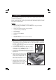
CHECK LIST Before attempting to assemble and use the tiling cutter, carefully unpack and lay out the contents on a clean surface. Check for missing/damaged parts. If any shortages or damage is found, please notify your Clarke dealer where the cutter was purchased ASAP, alternatively telephone Clarke International on 020-8988-7400. CONTENTS Note: Item Nos in brackets refer to parts diagram on page 9 • 4 x legs with rubber feet (75 & 74) + 4 x Screws (80), and 4 x Spring washers (79).
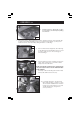
ASSEMBLY cont. 6. Install the pump by clipping into position as shown in Fig. 3, ensure the pump tubing is not kinked. Fig. 3 7. Once the pump is clipped firmly into position, carefully lower the cutter assembly into position in the water tank taking care not to trap the pump tubing or pump power lead. Check the cutter assembly is sitting flat before continuing. Fig. 4 8. Remove the head securing knob, arrowed in Fig.
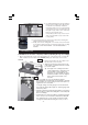
Fig. 7 11. Two Head Transverse Stops are provided on the top of the machine. These allow head movement to be restricted, as desired. Thread the slides on to the screw threads of the transverse stops, ensurintg they are the right way up, then screw on the stop knobs as shown in Fig.7 Fig. 7 Temporarily position stops, one at each end of the unit and loosely secure with locking knobs. 12. Screw the plug into the hole in the water tank, ensuring the rubber washer is beneath the tank. 13.
DO NOT force the head. Maintain the maximum disc speed at all times, allow the tool to do the work. Always cut in a straight line and DO NOT attempt to cut a curved line. Keep hands well clear of the disk whilst it is in motion. Remove all pieces using a scrap piece of wood, or similar, before making the next cut. 5. To stop the machine at any time, press the red button on the switch panel marked ‘O’. NEVER attempt to slow the machine quickly by putting excess pressure on the disk.
PARTS DIAGRAM -10-
PARTS LIST No.