
Specifications


-6-
CHECK LIST
Before attempting to assemble and use the tiling cutter, carefully unpack and lay out the
contents on a clean surface.
Check for missing/damaged parts. If any shortages or damage is found, please notify your
Clarke dealer where the cutter was purchased ASAP, alternatively telephone Clarke
International on 020-8988-7400.
CONTENTS
Note: Item Nos in brackets refer to parts diagram on page 9
• 4 x legs with rubber feet (75 & 74) + 4 x Screws (80), and 4 x Spring washers (79).
• 1 x Base frame (77).
• 1 x Main cutter assembly, includes cutting disk (fitted).
• 1 x Adjustable Guide ( 1 & 45 to 54)
• 2 x Stop (1, 2 & 3).
• 1 x Water tray (73).
• 2 x Retaining Clamp (28 & 76).
• 2 x Wrench.
• 1 x Hexagon Wrench.
• 1 x Operation and Maintenance Instruction Manual.
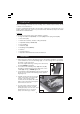
ASSEMBLY
1. Attach the legs to the base unit using the screws and washers supplied, do not tighten
screws until all four screws are fitted finger tight, once the four legs are loosely fitted rest
the stand on a firm flat surface.
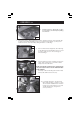
4. Carefully rest the main body of the tile
cutter on the edge of the water tank
as in Fig. 2 (also see Fig. 3 pump
location). Ensure the pump with cable
and hose are routed down through the
hole in the base as shown.
5. Hook the edge of the pump into the
side bracket as shown at ‘A’ whilst
pivoting the pump as shown at ‘B’, and
finally pressing home to secure the
pump as shown in Fig 3 overleaf.
Proceed to tighten all the leg securing screws with hex key
provided, DO NOT overtighten.
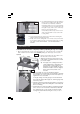
2. Loosely attach the retaining clamps (76) with bolts (81)
inserted from inside the base and securing knobs on the
outside (28) as in fig. 1, DO NOT tighten yet.
3. Lay the plastic water tank (73) into the base unit ensuring it
sits flat, secure in position with retaining clamps, tighten
finger tight only.
Fig. 1
Fig. 2