
Specifications


-7-
ASSEMBLY cont.
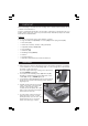
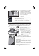
6. Install the pump by clipping into position
as shown in Fig. 3, ensure the pump tubing
is not kinked.
7. Once the pump is clipped firmly into position, carefully lower the cutter assembly into
position in the water tank taking care not to trap the pump tubing or pump power
lead. Check the cutter assembly is sitting flat before continuing.
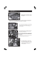
8. Remove the head securing knob, arrowed in Fig.
4, This will free the head and allow it to be moved
in order to gain access to the securing post,
arrowed in Fig. 5.
Fig. 4
Fig. 5
Fig. 3
10. To prevent damage to the electrical
input cable and the coolant hose, they
are encased in a flexible track. The track
needs to be secured at the motor end
as indicated in Fig.6, using the two
screws provided
9. Unscrew and remove the securing post and, store
safely, with securing nut, for use if the cutter is
transported at a later date.
NOTE: removing the securing post is optional, and is
only necessary in order to use the maximum table
width available.
Carefully continue traversing the head towards
the R/H side until it reaches the stop.
Fig. 6