E Operator's Manuals Image 16 120V (click here) Image 20 120V (click here)
E Operator's Manual Manuel d'utilisation Libro de Instrucciones IMAGE 16 120V READ THIS BOOK This book has important information for the use and safe operation of this machine. Failure to read this book prior to operating or attempting any service or maintenance procedure to your Clarke Technology machine could result in injury to you or to other personnel; damage to the machine or to other property could occur as well. You must have training in the operation of this machine before using it.
Table of Contents Operator Safety Instructions ............................................................................................................. 5 Introduction & Machine Specifications .............................................................................................. 8 120 Volt, 50/60 Cycle Machines Grounding Instructions ................................................................... 11 Machine Controls ...........................................................................
Image 16 120V LEA ESTE LIBRO Contiene información importante para el uso correcto y seguro de la máquina. Lea este libro completamente antes de arrancar la máquina o hacer cualquier operación de mantenimiento. Si no siga las instrucciones, corre el peligro de herirse o causar lesiones al personal, o causar daños importantes a la máquina o a su entorno. Antes de usar la máquina, es indispensable seguir una formación.
Image 16 120V Lisez ce manuel Il contient des informations importantes pour une utilisation correcte de la machine, en toute sécurité. Lisezle complètement avant de mette la machine en marche ou d’effectuer un entretien. A défaut, vous risqueriez de vous blesser ou de blesser d’utres membres du personnel, k’endommager sérieusement la machine ou de provoquer des dégâts dans son environnement. Avant de se servir de la machine, il est indispensable d’avoir reçu une formation.
IMPORTANT SAFETY INSTRUCTIONS WARNING AVERTISSEMENT ADVERTENCIA DANGER: Failure to read and observe all DANGER statements could result in severe bodily injury or death. Read and observe all DANGER statements found in your Owner's Manual and on your machine. WARNING: Failure to read and observe all WARNING statements could result in injury to you or to other personnel; property damage could occur as well. Read and observe all WARNING statements found in your Owner's Manual and on your machine.
INSTRUCCIONES DE SEGURIDAD INSTRUCCIONES PARA LA SEGURIDAD DEL OPERADOR WARNING AVERTISSEMENT AVISO PELIGRO: Si no siga las instrucciones que siguen la palabra PELIGRO, se pueden causar lesiones graves, incluso mortales. Lea y siga todas las instrucciones PELIGRO que se encuentran en el libro y en la máquina. AVISO: Si no siga las instrucciones AVISO, se pueden causar lesiones sea al operador sea a otro persona y/o daños materiales.
IMPORTANTES MESURES DE SECURITE AVERTISSEMENT: Pour réduire les risques d'incendie,de choc électrique ou de blessure: 1. Ne pas laisser l'appareil sans surveillance lorsqu'il est branché. Débrancher lorsque l'appareil n'est pas utilisé et avant l'entretien. 2. Pour réduire les risques de choc électrique, utiliser à l'intérieur seulement. 3. Ne pas permettre aux enfants de jouer avec l'appareil. Une attention particuliére est 4.
DANGER: Machines can cause an explosion when operated near flammable materials and vapors. Do not use this machine with or near fuels, grain dust, solvents, thinners, or other flammable materials. WARNING: You must have training in the operation of this machine before using it. READ THE INSTRUCTION BOOK FIRST. WARNING: Do not use this machine as a step or furniture. Injury could occur to the operator. WARNING: To avoid serious injury, use proper lifting procedures when lifting the machine.
¡ PELIGRO !: Las máquinas pueden originar una explosión cuando se operan cerca de materiales o vapores inflamables. No use nunca la máquina con o cerca de combustibles, polvo de granos, disolventes, diluyentes u otros materiales inflamables. AVISO: Usted debe seguir una formación antes de usar la máquina. LEA ESTE LIBRO DE INSTRUCCIONES ANTES DE ARRANCAR LA MÁQUINA. AVISO: No use esta máquina como escabel o mueble. El operador puede herirse.
! DANGER !: Les machines peuvent provoquer une explosion si elles sont utilisées dans l’environnement immédiat de matériaux ou de vapeurs inflammables. N’utilisez jamais la machine avec ou près de combustibles, de grains de poussière, de solvants, de diluants ou d’autres matériaux inflammables. AVERTISSEMENT: Vous devez avoir reçu une formation avant d’utiliser la machine. LISEZ LE MANUEL D’INSTRUCTIONS AVANT DE VOUS SERVIR DE LA MACHINE.
0 VOLT, 50/60 CYCLE MACHINES GROUNDING INSTRUCTIONS This product must be grounded. If it should malfunction or breakdown, grounding provides a path of least resistance for electric current to reduce the risk of electric shock. This product is equipped with a cord having an equipment-grounding conductor and grounding plug. The plug must be inserted into an appropriate outlet that is properly installed and grounded in accordance with all local codes and ordinances.
Maquina 120 Voltio, 50/60 ciclos Instrucciones para la puesta a tierra Esta máquina debe ser puesta a tierra. En caso de mal funcionamiento o avería, el hilo de tierra es un camino de menor resistencia para la corriente eléctrica; por lo cual se reduce el riesgo de choque eléctrico. La máquina tiene un cable de alimentación con un hilo de tierra y un enchufe con puesta a tierra.
Machine 120 Volt, 50/60 cycles Instructions pour la mise à la terre La machine doit être reliée à la terre. En cas de dysfonctionnement ou de pannes, la terre constitue une voie de moindre résistance pour le courant électrique, réduisant ainsi le risque d’électro-choc. Ce produit est équipé d’un câble d’alimentation comprenant un fil de terre et une fiche avec mise à la terre.
THE CONTROLS The Vacuum/Accessory Switch This switch is located on the left side of the control panel. To turn the vacuum motor and pump motor on, press the bottom of the switch. To turn the vacuum motor and pump motor off, press the top of the switch. The Spray/Brush Motor Switch The spray/brush switch is located in the center of the control handle. To turn on the spray/brush intermittently, press the top of the switch and hold for the length of time you want the floor spray/brush to run.
MANDOS Interruptor aspiración/bomba El interruptor (de tipo I/O - ON/OFF) se encuentra en el lado izquierdo del cuadro de mando. Para arrancar el motor de aspiración y el motor de la bomba, empuje la parte inferior del interruptor (posición I). Para parar los dos motores, empuje la parte superior del interruptor (posición O). Interruptor inyección/cepillo El interruptor se encuentra en el centro de la empuñadura.
HOW TO PREPARE THE MACHINE FOR OPERATION WARNING: This machine has moving parts. To reduce the risk of injury unplug before servicing. WARNING: To reduce the risk of fire, use only commercially available floor cleaners and waxes intended for machine application. WARNING: Do not use water that is hotter than 140° F. WARNING: Operating a machine that is not completely or fully assembled could result in injury or property damage. Do not operate this machine unless it is completely assembled.
PREPARACION DE LA MAQUINA PARA TRABAJAR PREPARATION DE LA MACHINE AVANT UTILISATION AVISO: Esta máquina tiene piezas móviles. Para evitar el peligro de lesiones, desconecte la máquina antes de cualquier mantenimiento. AVERTISSEMENT: Cette machine comporte des pièces mobiles. Pour évitar tout risque de blessure, débranchez la machine avant tout entretien.
HOW TO CLEAN AN AREA OF CARPET 3 2 1 6 5 4 CAUTION: The recovery tank is equipped with an electric shut-off float switch. When the recovery tank becomes full, all electrical functions will automatically be shut off. Turn the vacuum/accessory and spray/brush switch to the "OFF" position before emptying the recovery tank. Note: When using the extractor to clean carpets, follow this procedure: 1.Do not walk on freshly cleaned carpets for at least four hours or until the carpet is dry to touch. 2.
PRODUCTO DE LIMPIEZA PARA ALFOMBRA ¡CUIDADO!: El depósito de recuperación está provisto de un flotador de parada eléctrico. Cuando el depósito está lleno, todas las funciones eléctricas se paran automáticamente. Ponga el interruptor aspiración/accesorios y el interruptor inyección/cepillo en la posición ‘O’ antes de vaciar el depósito de recuperación. NOTA: Siga estos consejos cuando limpia una alfombra con el extractor: 1.
HOW TO CLEAN AN AREA OF CARPET (cont.) How To Clean A Larger Area Of Carpet See figure 3. To clean a larger area of carpet, follow this procedure: 1. Begin at the right-hand corner of the carpet. 2. Make a pass halfway along the edge of the carpet. Pull the machine backward at a steady speed. 3. Move to the edge of the carpet. Make another pass next to your first pass. 4. As you make more passes, overlap one inch of the area already cleaned.
PRODUCTO DE LIMPIEZA PARA ALFOMBRA (cont.) NETTOYAGE D’UN TAPIS (cont.) Limpieza de una superficie grande (véase fig. 3) Nettoyage d’une grande surface (voir fig. 3) Para limpiar una gran superficie de moqueta, siga este procedimiento: Pour le nettoyage d’une grande surface recouverte de moquette, procédez comme suit: 1. Empiece por el ángulo del lado superior de la alfombra. 2. Mueva la máquina a lo largo del borde derecho de la alfombra, hasta la mitad de su longitud.
How To Attach The Auxiliary Floor Tool To attach the auxiliary floor tool, follow this procedure: 1. Remove the vacuum hose from the recovery tank. 2. Connect the auxiliary floor tool vacuum hose to the recovery tank and to the auxiliary tool. 3. Connect the solution hose to the machine and to the tool. 4. Turn the vacuum/accessory switch "I". 5. Operate the optional cleaning tool as normal. 6. When finished cleaning with the optional floor tool, turn the vacuum/accessory switch "O".
SUJECION DE LOS ACCESORIOS OPCIONALES PARA EL SUELO FIXATION DES ACCESSOIRES POUR LE SOL EN OPTION Para sujetar los accesorios para el suelo, siga este procedimiento: 1. Quite el flexible de aspiración del depósito de recuperación. 2. Conecte el flexible de aspiración de los accesorios para el suelo con el depósito de recuperación y con el accesorio elegido. 3. Conecte el flexible del depósito de solución con la máquina y con el accesorio para el suelo. 4.
MAINTENANCE (cont.) How to Prevent Damage From Freezing Temperatures To prevent damage from freezing temperatures, follow this procedure: 1. Remove any solution remaining in the solution tank. 2. Make sure the machine and pump are completely dry. 3. Pour windshield-type antifreeze into the solution tank until the screen in the bottom of the filter is covered. 4. Turn on the vacuum/accessory and spray/brush switch for 30 seconds. 5. Remove antifreeze solution from the system before using the extractor. 6.
COMO PROTEGER LA MAQUINA DE LA HELADA COMMENT PROTEGER LA MACHINE CONTRE LE GEL Para evitar los daños causados por la helada, sírvase seguir el procedimiento siguiente: 1. Vaciar completamente el depósito de solución. 2. Procure que la máquina y la bomba sean perfectamente secas. 3. Eche el anticongelante (tipo ‘parabrisas’) en el depósito de solución hasta que el tamiz en el fondo del filtro sea completamente tapado. 4. Active el interruptor aspiración/bomba durante 30 segundos. 5.
NOTES Page 26 CLARKE TECHNOLOGY Image 16 Operator's Manual
IMAGE 16 120V Section II Parts and Service Manual (78486B) CLARKE TECHNOLOGY Image 16 Operator's Manual Page 27
AUTHORIZED PERSONNEL MAINTENANCE To Access Pump Motor 1. Remove brush housing from machine. See "Brush Motor Repair". 2. Remove pump ground wire from ground screw. 3. Disconnect pump electrical wires form machine harness. 4. Remove solution hoses by turning swivel nut counter clockwise. 5. Remove four (4) mounting screws that secure pump motor to solution tank. 6. Reverse procedures for installing new pump. Check wiring diagram for proper connections when reinstalling electrical parts.
MANTENIMIENTO EFECTUADO POR UN TECNICO AUTORIZADO Acceso al motor de la bomba 1. Saque el alojamiento del cepillo. Véase a continuación, sección ‘Reparación del motor del cepillo’. 2. Afloje el tornillo y quite el cable de puesta a tierra de la bomba. 3. Quite los cables de conexión de la bomba del haz de cables eléctricos. 4. Saque los flexibles de solución, girando el tornillo sin cabeza con pivote redondeado en el sentido contrario de las agujas del reloj. 5.
AUTHORIZED PERSONNEL MAINTENANCE (cont.) Brush Drive Belt Replacement 1. Tilt machine on handle or place machine upside down. 2. Remove bottom brush plate. 3. Remove pivot screw on drive sprocket side. 4. Remove drive sprocket and replace belt. 5. Reassemble in reverse order. Maintenance of the Vacuum Motor This machine has a vacuum motor that uses carbon brushes. The carbon brushes in the motor must be checked every three months, or every 500 hours of operation, whichever comes first.
MANTENIMIENTO EFECTUADO POR UN TECNICO AUTORIZADO Reemplazo de la correa de arrastre 1. Vuelque la máquina sobre su empuñadura o vúelvela. 2. Quite la placa inferior del alojamiento del cepillo. 3. Quite el tornillo sin cabeza que se encuentra en el lado del piñón de arrastre. 4. Quite el piñón y cambie la correa. 5. Para volver a instalar la correa, siga el orden inverso de las operaciones arriba mencionadas.
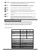
HOW TO CORRECT PROBLEMS IN THE MACHINE PROBLEM CAUSE ACTION The machine will not run. 1. Machine does not have power... 1. Make sure the machine is connected to the correct frequency and voltage, and all connections are tight. There is no suction. 1. Vacuum motor may not be running... 1. Be sure the vacuum/accessory switch for the vacuum motor is at the “ON” position. 2. Vacuum/accessory motor switch may be defective. 3. There may be a loose motor connection.. 3.
POSIBLES PROBLEMAS Y SOLUCIONES Problema Causa Solución La máquina no funciona 1. La máquina no está alimentada 1. Compruebe si la máquina está conectada con una red cuyas tensión y frecuencia son correctas y compruebe si todas las conexiones están correctamente apretadas No hay aspiración 1. El motor de aspiración no funciona 1. Compruebe que el interruptor aspiración/bomba está en la posición “I” 2. El interruptor aspiración/bomba es defectuoso 2. Avise a un técnico autorizado 3.
SOLUTION DE QUELQUES PROBLÉMES COURANTS Problème La machine ne fonctionne pas sur Cause probable Solution 1. La machine n’est pas alimentée 1. Vérifiez que la tension et la fréquence du système électrique lequel la machine est branchée correctes et que toutes les sont bien serrés 1. Le moteur d’aspiration ne fonctionne pas 2. L’interrupteur aspiration/ pompe est défectueux 3. Une connexion du moteur est détachée 4. Le flexible d’aspiration est obstrué 5. Les balais du moteur sont usés 6.
Authentic CLARKE TECHNOLOGY Products 6 5 4 3 2 1 Item Part No.
CLARKE TECHNOLOGY Image 16i/ix Drawing Final Assembly 4/99 3 19 18 11 16 20 15 12 21 10 13 22 4 14 23 44 49 1 37 26 28 5 39 40 41 38 47 25 24 32 27 30 31 51 29 35 34 42 17 48 46 17 45 6 38 36 43 9 33 50 45 2 7 8 Page 36 CLARKE TECHNOLOGY Image 16 Operator's Manual
CLARKE TECHNOLOGY Image 16i/ix Parts List, Final Assembly 4/99 Ref. Part No. Description 1 2 3 4 Page 38 Page 35 Page 34 Page 36 Page 37 912201 Page 39 59947A 920346 67463A 38996B 44911R 47708A 980603 962546 85736A 58533A 84237A 643418 962798 832322 81110A 692409 85519A 962113 980982 911933 47905A 45905C 45928A 77094A 920224 85383A 68779A 85395A 674110 872010 Page 39 47711A 87607A 980651 980652 85813A 53619A 59322A 171112 51518A 52414A 42911A 699203 67897A 51526A 980650 699202 14608A Asm.
CLARKE TECHNOLOGY Image 16i/ix Drawing & Parts List, Recovery Tank Assembly 2/99 Form #19183A 7 6 14 1 12 10 8 5 3 2 11 19 4 17 22 21 25 20 13 23 4 24 18 9 15 16 Page 38 Ref. Part No.
CLARKE TECHNOLOGY Image 16i/ix Drawing and Parts List, Brush Housing Assembly 5/01 Form #15718A 15 3 35 32 7 28 36 9 1 11 34 35 4 6 33 20 31 5 16 19 15 22 38 21 23 24 10 29 26 2 22 27 13 26 37 17 17a 30 18 25 8 14 12 12A 21 20 15 NOTE: Kindicates a change has taken place since last publication of this manual. Ref. Part No. Description Qty Ref. Part No.
CLARKE TECHNOLOGY Image 16i Drawing and Parts List, Electric Assembly 5/01 Form #17653A 1 22 9 2 17 8 16 10 20 4 15 19 3 18 6 7 7 23 13 21 14 24 5 12 11 Ref. Part No. Description Qty 1 85815A Screw, 5/16" x 1½ 2 980692 Washer, 5/16" Flat 3 34809B Handle, Control 4 47411A Switch, Vacuum/Accessories 5 47412A Switch, Spray/Brush 6 84237A Screw, 10-32 x ½ 7 85383A Screw, 10-32 x ¾ 8 980603 Washer, #10 Ext.
CLARKE Image 16ix Drawing and Parts List, Electric Assembly 5/01 Form #17652A 1 9 30 17 2 8 16 10 18 4 19 20 15 3 31 7 6 28 24 7 33 13 21 5 22 23 29 11 27 25 26 12 NOTE: Kindicates a change has been made since the last publication of this manual. Ref. Part No.
CLARKE TECHNOLOGY Image 16i/ix Drawing and Parts List, Recovery Shoe Assembly 8/00 Form # 19221A/19223A 4 17 11 8 2 5 1 7 9 10 18 6 9A 10 16 8 15 14 3 13 12, 12A Page 42 Ref. Part No. Description Qty i ix 1 2 3 4 5 6 7 8 9 9A 10 11 12 12a 13 14 15 16 17 18 28204B 53607A 67615A 872010 36505A 696801 63063A 962798 54880A 54164A 81110A 30426A 54339A 30042A 54157A 962333 49067A 980603 63061C 30076A Shoe, Recovery Elbow, ¼ St Shoe, Recovery S.S.
CLARKE TECHNOLOGY Image 16 Drawing and Parts List, Valve Assembly 5/01 Form #19411A 1 21 28 20 1 19 12 1 1 5 2 18 1 23 22 9 2 1 10 14 1 18 27 24 16 15 16 15 26 19 3 7 4 6 5 16 15 25 17 1 16 15 11 26 14 12 1 8 13, 13a, 13b, 13c Ref. Part No. Description Qty Ref. Part No.
CLARKE TECHNOLOGY Image 16 Drawing and Parts List 6/95 Pump (#45905C) i model Pump (45928A) ix model 4 3 2 1 7 6 Ref. Part No.
CLARKE TECHNOLOGY Image 16 Drawing and Parts List 6/95 Motor (#44911R) 13 19 2 4 14 6 3 15 5 16 7 18 8 9 14 15 20 10 11 21 12 17 22 1 Ref. 1* 2* 3* 4 5 6 7 8* 9 10* 11* 12* 13* Part No. 85303A 40812A 51914A 50618A 672714 Description Nut Housing Vent Fan Screw, 8-32 x 3/8 Brush, Mechanism Clamp Bracket, End, Com. Bearing Disc Bearing Washer Bracket, Fan End Spacer CLARKE TECHNOLOGY Image 16 Operator's Manual Qty Ref. 1 1 1 4 2 2 1 1 1 1 1 1 1 14* 15* 16* 17* 18 19 20* 21* 22* Part No.
Brush Circuit Breaker = 2.5 amp Fuse = 1.
CLARKE TECHNOLOGY Image 16 i/ix Connection Diagram 4/99 CLARKE TECHNOLOGY Image 16 Operator's Manual Page 47
NOTES
ALTO® PRODUCT SUPPORT BRANCHES U. S. A. Locations HEAD OFFICE European Locations PRODUCTION FACILITIES ALTO U.S. Inc., St. Louis, Missouri 16253 Swingley Ridge Road, Suite 200 Chesterfield, Missouri 63017-1725 PRODUCTION FACILITIES ALTO U.S. Inc., Springdale, Arkansas 2100 Highway 265 Springdale, Arkansas 72764 (501) 750-1000 Customer Service - 1-800-253-0367 Technical Service - 1-800-356-7274 ALTO U.S. Inc., Bowling Green, Ohio 43402 1100 Haskins ALTO U.S. Inc., Clearwater, Florida 33765 1500 N.
CLARKE TECHNOLOGY U.S. WARRANTY This Clarke Technology Industrial/Commercial Product is warranted to be free from defects in materials and workmanship under normal use and service for a period of one year from the date of purchase, when operated and maintained in accordance with Clarke Technology's Maintenance and Operations Instructions. This warranty is extended only to the original purchaser for use of the product.
E Operator's Manual Manuel d'utilisation Libro de Instrucciones IMAGE 20 120V READ THIS BOOK This book has important information for the use and safe operation of this machine. Failure to read this book prior to operating or attempting any service or maintenance procedure to your Clarke Technology machine could result in injury to you or to other personnel; damage to the machine or to other property could occur as well. You must have training in the operation of this machine before using it.
Image 20 120V Table of Contents Operator Safety Instructions ............................................................................................................. 5 Introduction & Machine Specifications .............................................................................................. 8 120 Volt, 50/60 Cycle Machines Grounding Instructions ................................................................... 11 Machine Controls .............................................................
Image 20 120V LEA ESTE LIBRO Contiene información importante para el uso correcto y seguro de la máquina. Lea este libro completamente antes de arrancar la máquina o hacer cualquier operación de mantenimiento. Si no siga las instrucciones, corre el peligro de herirse o causar lesiones al personal, o causar daños importantes a la máquina o a su entorno. Antes de usar la máquina, es indispensable seguir una formación.
Image 20 120V Lisez ce manuel Il contient des informations importantes pour une utilisation correcte de la machine, en toute sécurité. Lisezle complètement avant de mette la machine en marche ou d’effectuer un entretien. A défaut, vous risqueriez de vous blesser ou de blesser d’utres membres du personnel, k’endommager sérieusement la machine ou de provoquer des dégâts dans son environnement. Avant de se servir de la machine, il est indispensable d’avoir reçu une formation.
IMPORTANT SAFETY INSTRUCTIONS WARNING AVERTISSEMENT ADVERTENCIA DANGER: Failure to read and observe all DANGER statements could result in severe bodily injury or death. Read and observe all DANGER statements found in your Owner's Manual and on your machine. WARNING: Failure to read and observe all WARNING statements could result in injury to you or to other personnel; property damage could occur as well. Read and observe all WARNING statements found in your Owner's Manual and on your machine.
INSTRUCCIONES DE SEGURIDAD INSTRUCCIONES PARA LA SEGURIDAD DEL OPERADOR WARNING AVERTISSEMENT AVISO PELIGRO: Si no siga las instrucciones que siguen la palabra PELIGRO, se pueden causar lesiones graves, incluso mortales. Lea y siga todas las instrucciones PELIGRO que se encuentran en el libro y en la máquina. AVISO: Si no siga las instrucciones AVISO, se pueden causar lesiones sea al operador sea a otro persona y/o daños materiales.
IMPORTANTES MESURES DE SECURITE AVERTISSEMENT: Pour réduire les risques d'incendie,de choc électrique ou de blessure: 1. Ne pas laisser l'appareil sans surveillance lorsqu'il est branché. Débrancher lorsque l'appareil n'est pas utilisé et avant l'entretien. 2. Pour réduire les risques de choc électrique, utiliser à l'intérieur seulement. 3. Ne pas permettre aux enfants de jouer avec l'appareil. Une attention particuliére est 4.
DANGER: Machines can cause an explosion when operated near flammable materials and vapors. Do not use this machine with or near fuels, grain dust, solvents, thinners, or other flammable materials. WARNING: You must have training in the operation of this machine before using it. READ THE INSTRUCTION BOOK FIRST. WARNING: Do not use this machine as a step or furniture. Injury could occur to the operator. WARNING: To avoid serious injury, use proper lifting procedures when lifting the machine.
¡ PELIGRO !: Las máquinas pueden originar una explosión cuando se operan cerca de materiales o vapores inflamables. No use nunca la máquina con o cerca de combustibles, polvo de granos, disolventes, diluyentes u otros materiales inflamables. AVISO: Usted debe seguir una formación antes de usar la máquina. LEA ESTE LIBRO DE INSTRUCCIONES ANTES DE ARRANCAR LA MÁQUINA. AVISO: No use esta máquina como escabel o mueble. El operador puede herirse.
! DANGER !: Les machines peuvent provoquer une explosion si elles sont utilisées dans l’environnement immédiat de matériaux ou de vapeurs inflammables. N’utilisez jamais la machine avec ou près de combustibles, de grains de poussière, de solvants, de diluants ou d’autres matériaux inflammables. AVERTISSEMENT: Vous devez avoir reçu une formation avant d’utiliser la machine. LISEZ LE MANUEL D’INSTRUCTIONS AVANT DE VOUS SERVIR DE LA MACHINE.
120 VOLT, 50/60 CYCLE MACHINES GROUNDING INSTRUCTIONS This product must be grounded. If it should malfunction or breakdown, grounding provides a path of least resistance for electric current to reduce the risk of electric shock. This product is equipped with a cord having an equipment-grounding conductor and grounding plug. The plug must be inserted into an appropriate outlet that is properly installed and grounded in accordance with all local codes and ordinances.
Maquina 120 Voltio, 50/60 ciclos Instrucciones para la puesta a tierra Esta máquina debe ser puesta a tierra. En caso de mal funcionamiento o avería, el hilo de tierra es un camino de menor resistencia para la corriente eléctrica; por lo cual se reduce el riesgo de choque eléctrico. La máquina tiene un cable de alimentación con un hilo de tierra y un enchufe con puesta a tierra.
Machine 120 Volt, 50/60 cycles Instructions pour la mise à la terre La machine doit être reliée à la terre. En cas de dysfonctionnement ou de pannes, la terre constitue une voie de moindre résistance pour le courant électrique, réduisant ainsi le risque d’électro-choc. Ce produit est équipé d’un câble d’alimentation comprenant un fil de terre et une fiche avec mise à la terre.
THE CONTROLS The Vacuum/Accessory Switch This switch is located on the left side of the control panel. To turn the vacuum motor and pump motor on, press the bottom of the switch. To turn the vacuum motor and pump motor off, press the top of the switch. The Spray/Brush Motor Switch The spray/brush switch is located in the center of the control handle. To turn on the spray/brush intermittently, press the top of the switch and hold for the length of time you want the floor spray/brush to run.
MANDOS Interruptor aspiración/bomba El interruptor (de tipo I/O - ON/OFF) se encuentra en el lado izquierdo del cuadro de mando. Para arrancar el motor de aspiración y el motor de la bomba, empuje la parte inferior del interruptor (posición I). Para parar los dos motores, empuje la parte superior del interruptor (posición O). Interruptor inyección/cepillo El interruptor se encuentra en el centro de la empuñadura.
HOW TO PREPARE THE MACHINE FOR OPERATION WARNING: This machine has moving parts. To reduce the risk of injury unplug before servicing. WARNING: To reduce the risk of fire, use only commercially available floor cleaners and waxes intended for machine application. WARNING: Do not use water that is hotter than 140° F. WARNING: Operating a machine that is not completely or fully assembled could result in injury or property damage. Do not operate this machine unless it is completely assembled.
PREPARACION DE LA MAQUINA PARA TRABAJAR PREPARATION DE LA MACHINE AVANT UTILISATION AVISO: Esta máquina tiene piezas móviles. Para evitar el peligro de lesiones, desconecte la máquina antes de cualquier mantenimiento. AVERTISSEMENT: Cette machine comporte des pièces mobiles. Pour évitar tout risque de blessure, débranchez la machine avant tout entretien.
HOW TO CLEAN AN AREA OF CARPET 3 2 1 6 5 4 CAUTION: The recovery tank is equipped with an electric shut-off float switch. When the recovery tank becomes full, all electrical functions will automatically be shut off. Turn the vacuum/accessory and spray/brush switch to the "OFF" position before emptying the recovery tank. Note: When using the extractor to clean carpets, follow this procedure: 1.Do not walk on freshly cleaned carpets for at least four hours or until the carpet is dry to touch. 2.
PRODUCTO DE LIMPIEZA PARA ALFOMBRA ¡CUIDADO!: El depósito de recuperación está provisto de un flotador de parada eléctrico. Cuando el depósito está lleno, todas las funciones eléctricas se paran automáticamente. Ponga el interruptor aspiración/accesorios y el interruptor inyección/cepillo en la posición ‘O’ antes de vaciar el depósito de recuperación. NOTA: Siga estos consejos cuando limpia una alfombra con el extractor: 1.
HOW TO CLEAN AN AREA OF CARPET (cont.) How To Clean A Larger Area Of Carpet See figure 3. To clean a larger area of carpet, follow this procedure: 1. Begin at the right-hand corner of the carpet. 2. Make a pass halfway along the edge of the carpet. Pull the machine backward at a steady speed. 3. Move to the edge of the carpet. Make another pass next to your first pass. 4. As you make more passes, overlap one inch of the area already cleaned.
PRODUCTO DE LIMPIEZA PARA ALFOMBRA (cont.) NETTOYAGE D’UN TAPIS (cont.) Limpieza de una superficie grande (véase fig. 3) Nettoyage d’une grande surface (voir fig. 3) Para limpiar una gran superficie de moqueta, siga este procedimiento: Pour le nettoyage d’une grande surface recouverte de moquette, procédez comme suit: 1. Empiece por el ángulo del lado superior de la alfombra. 2. Mueva la máquina a lo largo del borde derecho de la alfombra, hasta la mitad de su longitud.
How To Attach The Auxiliary Floor Tool To attach the auxiliary floor tool, follow this procedure: 1. Remove the vacuum hose from the recovery tank. 2. Connect the auxiliary floor tool vacuum hose to the recovery tank and to the auxiliary tool. 3. Connect the solution hose to the machine and to the tool. 4. Turn the vacuum/accessory switch "I". 5. Operate the optional cleaning tool as normal. 6. When finished cleaning with the optional floor tool, turn the vacuum/accessory switch "O".
SUJECION DE LOS ACCESORIOS OPCIONALES PARA EL SUELO FIXATION DES ACCESSOIRES POUR LE SOL EN OPTION Para sujetar los accesorios para el suelo, siga este procedimiento: 1. Quite el flexible de aspiración del depósito de recuperación. 2. Conecte el flexible de aspiración de los accesorios para el suelo con el depósito de recuperación y con el accesorio elegido. 3. Conecte el flexible del depósito de solución con la máquina y con el accesorio para el suelo. 4.
MAINTENANCE (cont.) How to Prevent Damage From Freezing Temperatures To prevent damage from freezing temperatures, follow this procedure: 1. Remove any solution remaining in the solution tank. 2. Make sure the machine and pump are completely dry. 3. Pour windshield-type antifreeze into the solution tank until the screen in the bottom of the filter is covered. 4. Turn on the vacuum/accessory and spray/brush switch for 30 seconds. 5. Remove antifreeze solution from the system before using the extractor. 6.
COMO PROTEGER LA MAQUINA DE LA HELADA COMMENT PROTEGER LA MACHINE CONTRE LE GEL Para evitar los daños causados por la helada, sírvase seguir el procedimiento siguiente: 1. Vaciar completamente el depósito de solución. 2. Procure que la máquina y la bomba sean perfectamente secas. 3. Eche el anticongelante (tipo ‘parabrisas’) en el depósito de solución hasta que el tamiz en el fondo del filtro sea completamente tapado. 4. Active el interruptor aspiración/bomba durante 30 segundos. 5.
NOTES
Image 20 120V Section II Parts and Service Manual (78594A )
AUTHORIZED PERSONNEL MAINTENANCE To Access Pump Motor 1. Remove brush housing from machine. See "Brush Motor Repair". 2. Remove pump ground wire from ground screw. 3. Disconnect pump electrical wires form machine harness. 4. Remove solution hoses by turning swivel nut counter clockwise. 5. Remove four (4) mounting screws that secure pump motor to solution tank. 6. Reverse procedures for installing new pump. Check wiring diagram for proper connections when reinstalling electrical parts.
MANTENIMIENTO EFECTUADO POR UN TECNICO AUTORIZADO Acceso al motor de la bomba 1. Saque el alojamiento del cepillo. Véase a continuación, sección ‘Reparación del motor del cepillo’. 2. Afloje el tornillo y quite el cable de puesta a tierra de la bomba. 3. Quite los cables de conexión de la bomba del haz de cables eléctricos. 4. Saque los flexibles de solución, girando el tornillo sin cabeza con pivote redondeado en el sentido contrario de las agujas del reloj. 5.
AUTHORIZED PERSONNEL MAINTENANCE (cont.) Brush Drive Belt Replacement 1. Tilt machine on handle or place machine upside down. 2. Remove bottom brush plate. 3. Remove pivot screw on drive sprocket side. 4. Remove drive sprocket and replace belt. 5. Reassemble in reverse order. Maintenance of the Vacuum Motor This machine has a vacuum motor that uses carbon brushes. The carbon brushes in the motor must be checked every three months, or every 500 hours of operation, whichever comes first.
MANTENIMIENTO EFECTUADO POR UN TECNICO AUTORIZADO Reemplazo de la correa de arrastre 1. Vuelque la máquina sobre su empuñadura o vúelvela. 2. Quite la placa inferior del alojamiento del cepillo. 3. Quite el tornillo sin cabeza que se encuentra en el lado del piñón de arrastre. 4. Quite el piñón y cambie la correa. 5. Para volver a instalar la correa, siga el orden inverso de las operaciones arriba mencionadas.
HOW TO CORRECT PROBLEMS IN THE MACHINE PROBLEM CAUSE ACTION The machine will not run. 1. Machine does not have power... 1. Make sure the machine is connected to the correct frequency and voltage, and all connections are tight. There is no suction. 1. Vacuum motor may not be running... 1. Be sure the vacuum/accessory switch for the vacuum motor is at the “ON” position. 2. Vacuum/accessory motor switch may be defective. 3. There may be a loose motor connection.. 3.
POSIBLES PROBLEMAS Y SOLUCIONES Problema Causa Solución La máquina no funciona 1. La máquina no está alimentada 1. Compruebe si la máquina está conectada con una red cuyas tensión y frecuencia son correctas y compruebe si todas las conexiones están correctamente apretadas No hay aspiración 1. El motor de aspiración no funciona 1. Compruebe que el interruptor aspiración/bomba está en la posición “I” 2. El interruptor aspiración/bomba es defectuoso 2. Avise a un técnico autorizado 3.
SOLUTION DE QUELQUES PROBLÉMES COURANTS Problème La machine ne fonctionne pas sur Cause probable Solution 1. La machine n’est pas alimentée 1. Vérifiez que la tension et la fréquence du système électrique lequel la machine est branchée correctes et que toutes les sont bien serrés 1. Le moteur d’aspiration ne fonctionne pas 2. L’interrupteur aspiration/ pompe est défectueux 3. Une connexion du moteur est détachée 4. Le flexible d’aspiration est obstrué 5. Les balais du moteur sont usés 6.
Authentic CLARKE TECHNOLOGY Products 6 5 4 3 2 1 Item Part No.
CLARKE TECHNOLOGY Image 20i/ix Drawing Final Assembly 4/99 Form #04115A/04116A 3 19 18 35 11 16 15 20 12 21 10 13 4 22 14 23 44 49 1 26 37 42 27 17 48 28 5 39 40 41 38 38 47 25 52 24 34 6 43 30 13 8 45 36 33 51 9 7 46 35 17 45 35 13 31 50 34 29 32 2 35 Page 36 CLARKE TECHNOLOGY Image 20 Operator's Manual
CLARKE TECHNOLOGY Image 20i/ix Parts List, Final Assembly 4/99 Form #04115A/04116A Ref. Part No.
CLARKE TECHNOLOGY Image 20i/ix Drawing & Parts List, Recovery Tank Assembly 2/99 Form #19183A 7 6 14 1 12 10 8 5 3 2 11 19 4 17 13 22 21 25 23 20 4 24 18 9 15 16 Ref. Part No. Description 1 2 3 4 5 6 7 8 9 10 11 12 38982C 47419A 56459A 837304 692409 832322 962798 81110A 39326A 85519A 59877A 34256A Tank, Recovery Switch, Float Strain, Relief O'Ring Chain Cover, Solution Tank Screw, 10-24 x ½ Nut, 10-24 Tube, Vacuum Screw, ¼-20 x 3/8 Washer, ½ NPT Sealing Gasket, Cover Page 38 Qty Ref.
CLARKE TECHNOLOGY Image 20i/ix Form #15717A Drawing and Parts List, Brush Housing Assembly 8/00 15 3 39 35 32 5 37 35 37 36 7 28 1 9 11 4 6 31 33 19 16 15 40 20 16 21 22 23 24 10 20 26 2 38, 38A 18 21 22 25 33 8 17 18 17a 30 29 27 13 26 NOTE: Kindicates a change has taken place since last publication of this manual. 14 12 15 Ref. Part No. Description Qty Ref. Part No.
CLARKE TECHNOLOGY Image 20i Drawing and Parts List, Electric Panel Assembly 8/00 Form #17656A 1 22 2 9 17 16 8 10 4 20 15 19 3 18 23 6 7 13 14 21 5 12 11 Ref. Part No. Description Qty 1 85815A Screw, 5/16" x 1½ 2 980692 Washer, 5/16" Flat 3 34809B Handle, Control 4 47411A Switch, Vacuum/Accessories 5 47412A Switch, Spray/Brush 6 84237A Screw, 10-32 x ½ 7 85383A Screw, 10-32 x ¾ 8 980603 Washer, #10 Ext.
CLARKE TECHNOLOGY Image 20ix Drawing and Parts List, Electric Panel Assembly 8/00 Form #17436A 1 30 9 2 17 8 18 16 10 4 19 20 15 3 31 28 6 24 7 13 21 5 22 14 29 11 23 27 25 26 12 NOTE: Kindicates a change has taken place since last publication of this manual. Ref. Part No.
CLARKE TECHNOLOGY Image 20i/ix Drawing and Parts List, Recovery Shoe Assembly 8/00 Form # 19219A/19224A 4 17 8 11 2 5 1 7 9 10 18 9A 6 10 16 8 14 3 15 13 12 12a NOTE: Kindicates a change has taken place since last publication of this manual. Ref. Part No.
CLARKE TECHNOLOGY Image 20 Drawing and Parts List, Valve Assembly 4/99 Form #19411A1 21 28 20 1 19 12 1 1 5 2 18 1 23 22 9 2 16 15 16 15 26 1 1 18 19 27 24 10 14 3 7 4 6 5 16 15 25 17 1 16 15 11 26 14 12 1 13, 13a, 13b, 13c Ref. Part No.
CLARKE TECHNOLOGY Image 20 Drawing and Parts List 11/95 Pump (45905C) i model Pump (45928A) ix model 4 3 2 1 7 6 Ref. Part No.
CLARKE TECHNOLOGY Image 20 Drawing and Parts List 11/95 Motor (#44911R) 13 19 2 4 14 3 6 15 5 16 7 18 8 14 9 15 20 21 10 11 17 12 22 1 Ref. 1* 2* 3* 4 5 6 7 8* 9 10* 11* 12* 13* Part No. 85303A 40812A 51914A 50618A 672714 Description Nut Housing Vent Fan Screw, 8-32 x 3/8 Brush, Mechanism Clamp Bracket, End, Com. Bearing Disc Bearing Washer Bracket, Fan End Spacer CLARKE TECHNOLOGY Image 20 Operator's Manual Qty Ref. 1 1 1 4 2 2 1 1 1 1 1 1 1 14* 15* 16* 17* 18 19 20* 21* 22* Part No.
Brush Circuit Breaker = 2.5 AMP Fuse = 1.
CLARKE TECHNOLOGY Image 20i/ix Connection Diagram 4/99 CLARKE TECHNOLOGY Image 20 Operator's Manual Page 47
NOTES
ALTO® PRODUCT SUPPORT BRANCHES U. S. A. Locations HEAD OFFICE European Locations PRODUCITON FACILITIES ALTO U.S. Inc., St. Louis, Missouri 390 S. Woods Mill Rd., Suite 300 Chesterfield, Missouri 63017-3433 PRODUCTION FACILITIES ALTO U.S. Inc., Springdale, Arkansas 2100 Highway 265 Springdale, Arkansas 72764 (501) 750-1000 Customer Service - 1-800-253-0367 Technical Service - 1-800-356-7274 ALTO U.S. Inc., Bowling Green, Ohio 43402 1100 Haskins ALTO U.S. Inc., Clearwater, Florida 33765 1500 N.
CLARKE TECHNOLOGY WARRANTY This Clarke Technology Industrial/Commercial Product is warranted to be free from defects in materials and workmanship under normal use and service for a period of one year from the date of purchase, when operated and maintained in accordance with Clarke Technology's Maintenance and Operations Instructions. This warranty is extended only to the original purchaser for use of the product.