24L OIL FREE AIR COMPRESSOR MODEL NO: RANGER 6/240 PART NO: 2242010 OPERATION & MAINTENANCE INSTRUCTIONS LS1212
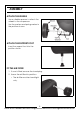
INTRODUCTION Thank you for purchasing this CLARKE 24L Oil Free Air Compressor. Please read this manual fully before use and follow the instructions carefully. In doing so you will ensure the safety of yourself and those around you, and you can look forward to your purchase giving you long and satisfactory service. GUARANTEE This product is guaranteed against faulty manufacture for a period of 12 months from the date of purchase. Please keep your receipt which will be required as proof of purchase.
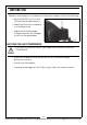
SAFETY PRECAUTIONS Before using your compressor it is in your own interest to read and pay attention to the following safety rules. 1. Compressed air is dangerous. Do not point a jet of air at persons or animals, and do not discharge compressed air against the skin. 2. DO NOT operate your compressor with the guard removed. 3. Repairs must only be carried out by a qualified engineer. If problems occur, contact your Clarke dealer. 4.
ELECTRICAL CONNECTIONS WARNING! Read these electrical safety instructions thoroughly before connecting the product to the mains supply. Connect the mains lead to a standard, 230 Volt (50Hz) electrical supply through an approved 13 amp BS 1363 plug, or a suitably fused isolator switch. If the plug has to be changed because it is not suitable for your socket, or because of damage, it must be removed and a replacement fitted, following the wiring instructions shown below.
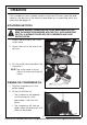
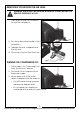
ASSEMBLY ATTACH THE WHEELS Use a suitable spanner to attach the wheels to the compressor. Use the washers and spring washer in the positions shown. ATTACH THE SUPPORT FOOT Insert the support foot into the position shown. FIT THE AIR FILTER 1. If one is fitted, remove the travel plug. 2. Screw the air filter into position. • The air filter must be hand tight only. 5 Parts & Service: 020 8988 7400 / E-mail: Parts@clarkeinternational.com or Service@clarkeinternational.
BEFORE USE Before connecting your compressor to the power supply, check the following:• Set the ON/OFF switch to the OFF position (pushed down). • Make sure that the compressor is on level ground. • Make sure that the supply voltage matches the voltage shown on the data label. MOVING THE AIR COMPRESSOR CAUTION: TO PREVENT INJURY, GET ASSISTANCE WHEN LIFTING THIS COMPRESSOR. • Stop the compressor and disconnect it from the power supply before you move it. • Always use the handle.
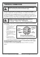
OPERATION If the compressor has not been used for more then 24 hours, open the drain valve (on the bottom of the reservoir) and drain any condensate which has collected. See page 10. ATTACHING AIR TOOLS WARNING: BEFORE CONNECTING AIR TOOLS, MAKE SURE THAT YOU READ THE INSTRUCTIONS SUPPLIED WITH THE TOOL, ALSO ENSURE THAT THE TOOL IS SUITABLE FOR USE WITH THE COMPRESSOR AND HOSE SPECIFICATIONS. 1. Attach the air hose to the ¼" BSP outlet valve. 2. Attach the tool to the end of the air hose. 3.
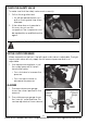
CHECK THE SAFETY VALVE To make sure that the safety valve works correctly. 1. Pull on the ring attached. • Air will be released when you pull on the ring and stop when released. 2. If the valve does not operate in this way, do not use the compressor. The compressor must be repaired by a qualified service agent. WARNING: DO NOT REMOVE OR TRY TO ADJUST THE SAFETY VALVE. SET THE OUTPUT PRESSURE When viewed from the front, the left hand outlet valve is adjustable.
REMOVING TOOLS FROM THE AIR HOSE WARNING: ALWAYS SET THE PRESSURE REGULATOR TO ZERO BEFORE YOU REMOVE OR REPLACE A TOOL. 1. Push down on the On/Off button to stop the compressor. 2. Turn the outlet valve handle to the off position. 3. Operate the tool to depressurise the air hose. 4. Disconnect the tool from the hose. TURNING THE COMPRESSOR OFF 1. Follow steps 1-3 in “Removing Tools From The Air Hose” above. 2. Disconnect the compressor from the power supply. 3.
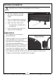
DRAINING THE RESERVOIR CAUTION: YOU MUST DRAIN THE RESERVOIR AFTER EACH DAYS USE AND BEFORE YOU PUT YOUR COMPRESSOR INTO STORAGE. 1. Turn the compressor off and disconnect from the power supply. 2. Put a container below the drain valve to collect the condensate. 3. Open the drain valve slowly. • Condensation will drain from the reservoir. 4. Close the drain valve when the reservoir has fully drained. RESET BUTTON This compressor has a thermal overload device.
MAINTENANCE DRAIN THE RESERVOIR (DAILY) After use, always open the drain valve to make sure that any condensate is drained off. CLEAN THE AIR FILTER (MONTHLY) The air filter must be examined monthly, more often in dusty conditions, 1. Remove the filter from the compressor. 2. Remove the filter cover from the filter. 3. Remove the filter from the filter cover. 4. Clean the sponge and the filter cover using a soft brush. • If necessary, the filter can be carefully cleaned in warm soapy water.
CHECK THE NON-RETURN VALVE (EVERY 6 MONTHS) If the reservoir pressure decreases for no apparent reason, it is possible that the non-return valve is leaking. To check, 1. Make sure that the reservoir is not under pressure and the compressor is switched OFF and disconnected from the power supply. 2. Examine the non-return valve, and replace the gasket and valve if necessary.
TROUBLESHOOTING CAUTION: DO NOT TRY TO REPAIR OR ADJUST THIS COMPRESSOR IF YOU ARE UNCERTAIN. IF YOU HAVE ANY QUERIES, CONTACT YOUR DEALER. PROBLEM PROBABLE CAUSE REMEDY The compressor has stopped and does not start. Bad electrical connections. 1. Check electrical connections. 2. Clean and tighten if necessary. Overload cutout switch has tripped. 1. Switch off and wait approx 5 minutes. 2. Press the reset button and switch on again. Motor windings burnt out. 1.
EXPLODED DIAGRAM 14 Parts & Service: 020 8988 7400 / E-mail: Parts@clarkeinternational.com or Service@clarkeinternational.
PARTS LIST No Description Part No No Description Part No No Description Part No 1 Bolt M6×25 HTRAN624001 35 Spring Washer HTRAN624035 70 Pressure Switch HTRAN624070 2 Bolt M6×35 HTRAN624002 36 Tooth Washer 4 HTRAN624036 71 Release Pipe HTRAN624071 3 Spring Washer HTRAN624003 37 Screw M3×6 HTRAN624037 4 Cylinder Head HTRAN624004 38 Spring Washer HTRAN624038 5 O Circle HTRAN624005 39 Nut M3 HTRAN624039 6 Valve Plate Subassembly HTRAN624006 40 Capacitance HTRAN
DECLARATION OF CONFORMITY 16 Parts & Service: 020 8988 7400 / E-mail: Parts@clarkeinternational.com or Service@clarkeinternational.
DECLARATION OF CONFORMITY 17 Parts & Service: 020 8988 7400 / E-mail: Parts@clarkeinternational.com or Service@clarkeinternational.
POPULAR ACCESSORIES 18 Parts & Service: 020 8988 7400 / E-mail: Parts@clarkeinternational.com or Service@clarkeinternational.
NOTES 19 Parts & Service: 020 8988 7400 / E-mail: Parts@clarkeinternational.com or Service@clarkeinternational.