S12, S16 S12cc, S12PF Operating Instructions and Repair Parts List Upright Vacuum READ THIS BOOK This book has important information for the use and safe operation of this machine. Failure to read this book prior to operating or attempting any service or maintenance procedure to your Clarke machine could result in injury to you or to other personnel; damage to the machine or to other property could occur as well. You must have training in the operation of this machine before using it.
Table of Contents Operator Safety Instructions ................................................................................... 3 Grounding Instructions ............................................................................................ 5 Consignes de sécurité de l'utilisateur ...................................................................... 6 Instructions visant la mise a la terra ........................................................................
OPERATOR SAFETY INSTRUCTIONS WARNING AVERTISSEMENT ADVERTENCIA For the safe operation of this machine, read and understand all dangers, warnings and cautions. Look for these symbols: DANGER: If you do not follow the instructions in a DANGER, severe bodily injury or death can occur to the operator and/or other personnel. WARNING: If you do not follow the instructions in a WARNING, injury can occur to you or to other personnel.
WARNING: To reduce the risk of fire, electric shock, or injury: 16. Belt pulleys can become hot during normal use. To prevent burns, avoid touching the belt pulley when servicing the drive belt. 17. Do not use to pick up flammable or combustible liquids such as gasoline, or use in areas where they may be present.
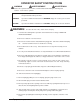
GROUNDING INSTRUCTIONS Grounded Outlet Box Preparation: The following are instructions for connection to the power supply and the electrical ground. This machine must be connected to the electrical ground to protect the operator from electrical shock. The machine has an approved power cord with three conductors and a plug with three terminals. Connect the plug to a receptacle that has three holes and is connected to the electrical ground.
CONSIGNES DE SÉCURITÈ DE L'UTILISATEUR AVERTISSEMENT Pour utiliser cet appareil en toute sécurité, il faut lire et coprendre tous les consignes de danger, d'avertissement et d'attention. Soyez attentif aux symboles que voici. DANGER: Ne pas respecter les consignes d'un avis de DANGER, peut occasionner la mort ou des lesions corporelles graves pour l'utilisateur et/ou d'autres pesonnes.
AVERTISSEMENT: Pour réduire le risque de feu, de choc électrique, ou de blessure: 16. Ne remassez pas de objets qui brûient ou fument comme les cigarettes, les allumettes ou les cendres chaudes. 17. Les poulies de la courroie peuvent devenir chaudes pendant l'utilisation normale. Pour prévenir des brûlures, évitez de toucher la poulie lors de l'entretien de la courroie.
INSTRUCTIONS VISANT LA MISE A LA TERRE PREPARATION: Consignes pour brancher l'appareil a la source d'energie et pour la mise à la terre. Boîte de Prise de Terre Cet appareil doit être mise à la terre afin d'eviter le risque de choc électrique. Cet appareil est pourvu d'un cordon muni de trois conducteurs et d'une fiche munie de trois bornes. Brancher la fiche à une prise qui a trois tous et est mise à la terre. Le conducteur vert (ou vert et jaune) dans le cordon est le fil neutre.
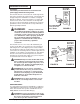
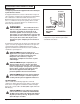
HOW TO PREPARE THE MACHINE FOR OPERATION Assemble the Handle Attach upper (A) and lower (B) handle to handle socket (C) by aligning holes and securing with 2 part screws (D). See figure 1. A D Install the Bag Assembly Position the bag coupling into the left bag support (A) and turn the bag knob (B) counterclockwise to secure bag to base. Attach bag spring to bag hook (C) located on the rear of the top cord hook. See figure 2.
MAINTENANCE This section describes the procedures that must be done by the operator. Motor Pulley WARNING: To prevent injury, always turn off the switch and remove the electrical plug from the electrical outlet before changing the brush, belt, or filter bag and before leaving the machine. WARNING: To prevent electrical shock, always turn off the switch and remove the electrical plug from the electrical outlet before doing any repairs or maintenance to this machine.
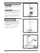
MAINTENANCE (CONT.) 9. Place the rubber end cap covers over both end caps (flat side against end cap). Align holes and secure. Then, slant the brush roll forward so the end caps are in line with the slots in the cleaner base. Push the brush roll into the base until seated. See figure 6. NOTE: Endcaps are color coded. 10. Place the lower side of the belt into the belt guide and around the left side of the motor pulley. See figure 7.
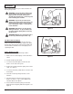
MAINTENANCE (CONT.) Steel Core Brush WARNING: Turn off the switch and disconnect unit from electrical supply before replacing brush strips. D 1. New brush strips inserts are supplied in sets. To replace, first disconnect the machine from the electrical outlet. C 2. Remove the brush roll, see the section "How to Replace the Belt." A B 3. Take the rubber end cap cover from the end of the brush roll. Figure 9 4. Remove end cap (figure 9, item A) and bearing retainer (figure 9, item B). 5.
TROUBLE SHOOTING GUIDE PROBLEM Motor does not run. POSSIBLE CAUSE 1) Not firmly plugged in. 2) Bad On-Off switch. 3) Line open. 4) Motor open. 5) Fan locked by material. SOLUTION 1) Check attachment plug. 2) Replace switch. 3) Replace cord. 4) Check motor and wiring. 5) Remove obstruction. Motor runs but cleaner does not pick up. 1) Belt broken. 2) Blocked air system. 3) Fan broken. 4) Worn brush roll. 5) Motor slow. 6) Bag full. 1) Replace belt. 2) Clean obstruction. 3) Replace fan.
Clarke® Upright Vacuum Collector Cup Assembly Drawing 9/02 Page -14- Clarke® Upright Vacuum Operator's Manual
Clarke® Upright Vacuum Collector Cup Assembly Parts List 2/04 Ref. Part No.
Clarke® Upright Vacuum Base Assembly Drawing 2/04 115 113 116 Page -16- Clarke® Upright Vacuum Operator's Manual
Clarke® Upright Vacuum Base Assembly Parts List 2/04 Ref. 1 2 3 4 5 6 7 8 9 10 11 12 13 14 15 16 17 18 19 20 21 22 23 24 25 26 27 28 29 30 31 32 33 34 35 36 37 Part No. Description 51229B 80065A 51949A 80066A 40624A 51348A 40642A 40643A 51230A 30161A 40178A 51245A 30157A 30135A 51256B 51259A 30152A 57951A 30151A 30098B 30099B 51270A 902648 30155A 51271A 56489A 51233A 51231A 51257B 51211A 53369A 51272B 51351A 56485A 30153B 51352B Qty. Ref. Hood and Graphics Screw (M4 *10) Cable Clip Screw (M4* 18.
Clarke® Upright Vacuum Handle and Filter Bag Assembly Drawing 9/02 Page -18- Clarke® Upright Vacuum Operator's Manual
Clarke® Upright Vacuum Handle and Filter Bag Assembly Parts List 6/03 Ref. 26 31 35 70 71 72 73 74 75 76 77 78 79 80 81 82 83 84 85 86 87 88 89 90 91 92 93 96 97 98 99 100 102 103 104 105 Part No.
NOTES Page -20- Clarke® Upright Vacuum Operator's Manual
CLARKE PRODUCT SUPPORT BRANCHES U. S. A.
Clarke® U.S. WARRANTY This Clarke Industrial/Commercial Product is warranted to be free from defects in materials and workmanship under normal use and service for a period of one year from the date of purchase, when operated and maintained in accordance with Clarke's Maintenance and Operations instructions. This warranty is extended only to the original purchaser for use of the product. It does not cover normal wear parts such as electrical cable, rubber parts, hoses and motor brushes.