SCRUBTEC 743 S SCRUBTEC 743 L SCRUBTEC 751 S SCRUBTEC 751 L SCRUBTEC 743 S C SCRUBTEC 743 L C Operator's Manual U.S. Patent No. 6,105,192; No. 6,557,207; No. 6,760,947 READ THIS BOOK CAUTION: Read the Operator's Manual before using the appliance. This book has important information for the use and safe operation of this machine.
Table of Contents Operator Safety Instructions ............................................................................................................................ 3 Machine Introduction ........................................................................................................................................ 4 Machine Specifications ....................................................................................................................................
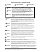
OPERATOR SAFETY INSTRUCTIONS WARNING AVERTISSEMENT ADVERTENCIA DANGER: Failure to read and observe all DANGER statements could result in severe bodily injury or death. Read and observe all DANGER statements found in the Operator's Manual and on the machine. WARNING: Failure to read and observe all WARNING statements could result in injury to you or to other personnel; property damage could occur as well. Read and observe all WARNING statements found in the Operator's Manual and on the machine.
WARNING: Maintenance and repairs performed by unauthorized personnel could result in damage or injury. Maintenance and repairs must be performed by authorized personnel only. WARNING: Any alterations or modifications to this machine could result in damage to the machine or injury to the operator or other bystanders. Alterations or modifications not authorized by the manufacturer voids any and all warranties and liabilities.
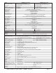
Model Machine Power Supply Pad or Brush Traverse Traverse Forward Speed Traverse Reverse Speed Battery Protection Motor Vacuum Solution Tank Solution Level Recovery Tank Recovery Full Indicator Parabolic Squeegee Squeegee Operation Cleaning Swath Motor, Brush Brush / Pad Size Brush Speed Brush Pressure Brush Solution Retention Drive Wheels Caster On-Board Charger Grade Cleaning Length Width Height Weight w/batteries (130AH) Shipping Weight w/Batteries (130AH) Line of Sight (Operator Height = 5'8") Noise Lev
Machine Specifications (S20 Rotary and L20 Rotary) Model Machine Power Supply SCRUBTEC 751 S Rotary SCRUBTEC 751 L Rotary 24 Volt D.C., (2) 12V 130AH Wet 24 Volt D.C., (2) 12V 130AH Wet or (2) 12V 100AH Gel Deep Cycle Batteries or (2) 12V 100AH Gel Deep Cycle Batteries Pad or Brush 3-Lug Driver Style 3-Lug Driver Style Traverse Brush Assist 1/3 HP (0.25 kW) Traverse Forward Speed Not Applicable Variable to 200 ft./min (61 m/min) Traverse Reverse Speed Not Applicable Variable to 140 ft./min.
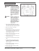
Procedures For Transporting How to Put the Machine Into a Van or Truck WARNING: This machine is heavy. Get assistance before attempting to transport or move it. Use two able persons to move the machine on a ramp or incline. Always move slowly. Do not turn the machine on a ramp. Do not stop and leave the machine on a ramp or incline. The loading ramp must be a minimum of 32" wide. WARNING: Machines can topple over if guided over the edges of stairs or loading docks and cause injury or damage.
Procedures For Transporting (cont.) 11. Fasten the machine to the vehicle. ALTO recommends a strap over the top of the machine and a strap to keep the machine from rolling forward or backwards. If this is not done, there is a possibility of the machine toppling over. Three tie down points are provided on the steel frame of the machine, for securing machine (see figure 2a). How to Remove the Machine From a Van or Truck 1. Make sure there are no obstructions in the area. 2.
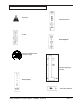
SYMBOLS USED ON SCRUBTEC 743 and 751 + Warning Solution Control Power Brush Up/Down Traverse Speed Control ("L Class" only) Vacuum/Squeegee Control Battery Meter AC Power Indicator CLARKE TECHNOLOGY Operator's Manual -SCRUBTEC 743 and 751 Page -9-
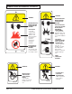
SYMBOLS USED ON SCRUBTEC 743 and 751 WARNING WARNING READ OPERATOR'S MANUAL BEFORE OPERATING THIS MACHINE READ OPERATOR'S MANUAL BEFORE OPERATING THIS MACHINE EXPLOSIVE GASES, CAN CAUSE SEVERE INJURY, DEATH OR DAMAGE TRANSFORMER. • Keep flammable materials away from batteries. Charge in a cool well ventilated area. RISK OF FIRE • Use only commercially available floor cleaners and waxes intended for machine operation. • Do not use flammable materials. 71018A BATTERIES CONTAIN SULFURIC ACID.
Machine Control Panel Electrical Power Indicator (See Figure 3, Item "A") A yellow light will be illuminated when the charger is plugged into an AC electrical outlet. The electrical cord must be unplugged and stowed before operating the machine. Key Switch (See Figure 3, Item "B") The key switch is standard on the "L" models. It is used primarily for preventing unauthorized use by removing the key.
Machine Control Panel Reverse Switch (See Figure 3, Item "H") On Traverse "L" Models Only - The reverse switch, when used in conjunction with one of the forward/ reverse switches, causes the machine to reverse directions. The reverse speed is 70% of the forward speed. G F H J K G E A Brush Motor Buttons (See Figure 3, Item "I") To lower brush head and activate brush motor(s) and solution flow, press and hold the down button until the green light is illuminated.
Machine Controls and Features Squeegee Lift Handle, See Figures 4 and 5 The squeegee lift handle is located in the control handle. It is used to raise or lower the squeegee. The vacuum motor is turned on when the handle is lowered to either the center or lowest position. Float Shut Off, See Figure 6 The shut-off switch for the vacuum motor is located in the recovery tank. It automatically turns off the vacuum motor when the recovery tank is full.
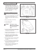
How To Prepare the Machine For Operation The Scrubtec machines use two 12-volt batteries. The batteries are located in the battery compartment under the recovery tank. It is recommended to remove the recovery tank when installing the batteries. How To Install The Batteries To install the batteries, follow this procedure: 1. Turn the machine off. Set brake (if equipped). Figure 7 2. Make sure the recovery tank is empty. NOTE: The recovery tank on the Scrubtec is designed for easy removal and cleaning. 3.
How To Prepare the Machine For Operation Place the batteries in the compartment shown in Figure 11. WARNING: WARNING: - + The batteries are heavy. Lifting batteries without help could result in an injury. Get help to lift the batteries. Working with batteries can be dangerous. Always wear eye protection and protective clothing when working near batteries. NO SMOKING! FRONT 9. - + Figure 11 10.
How To Prepare the Machine For Operation Battery Maintenance The electrical power to operate the machine comes from the storage batteries. Storage batteries need preventative maintenance. Correct Level To maintain the batteries in good condition, follow these instructions. 1. Keep the electrolyte at the correct level. The correct level is between 1/4" (1/2 cm) below the bottom of the tube in each cell and above the tops of the plates. Check the level of the electrolyte each time you charge the batteries.
How To Prepare the Machine For Operation How To Charge The Batteries WARNING: Charging the batteries in an area without adequate ventilation could result in an explosion. To prevent an explosion, charge the batteries only in an area with good ventilation. WARNING: Lead acid batteries generate gases which could explode. Keep sparks and flames away from batteries. NO SMOKING! To charge the batteries, follow this procedure: Figure 16 1. Place the machine on a flat-level surface with adequate ventilation. 2.
How To Prepare the Machine For Operation • Absorption Stage - In the absorption stage the red and green light will be illuminated on the charger (See Figure 17). During this stage the charger maintains constant voltage and lets the batteries absorb the charge at their own rate. • Float and Maintenance Stage - In the maintenance stage the red light turns off and only the green light will be illuminated on the charger (See Figure 17.
How To Prepare the Machine For Operation How To Remove Rotary Brush or Pad Driver (if equipped) To remove the brush or pad driver from the machine, follow this procedure: 1. Turn the key switch clockwise ("L" models only). Press the green "ON" button. 2. Raise the brush head by pressing and holding the brush up switch until brush head is in it's full up and rotated position. 3. Press the red "OFF" button or turn the key switch counterclockwise on machines equipped with key.
How To Operate The Machine How To Operate The Squeegee The squeegee wipes the floor while the vacuum motor removes the dirty solution from the floor. Use your hand to lower or raise the squeegee handle. To operate the squeegee, follow this procedure: 1. To lower the squeegee and start the vacuum motor, move the squeegee lever to the right and down (See figure 25). 2. To raise the squeegee, lift the squeegee lever up (See figure 26.
How To Operate The Machine 5. When either the left or right forward/reverse switches (figure 28, item A) are pushed in, the machine will go forward ("L" models only). 6. Control the speed of traverse by using the traverse speed control knob ("L" models only) (figure 28, Item C). B C A A 7. To stop, release the forward/reverse switch. 8.
How To Operate The Machine To pre-wet brushes you should first turn the speed knob to the lowest traverse setting on the "L" model. Then on both the "S" and "L" models, lower brushes until brushes are just touching the floor and the yellow light on the control panel in illuminated. Activate the forward/reverse switch to start motor and solution flow. NOTE: On the "L" model, the machine will not move when the traverse speed knob is rotated fully counterclockwise. 7.
Maintenance 5. Make sure the valve on the recovery drain hose is clean. Tightly close the valve. 6. Make sure the brush/pad is in position and installed correctly. 7. Make sure brush housing and skirts are in position on the brush head. 8. Check the installation of the squeegee and squeegee hose. 9. Make sure the solution drain / level indicator hose is secure on the storage mount on the rear of the machine. Figure 31 Do These Procedures When You End Your Work 1.
Maintenance 7. On machines with cylindrical brush head, the debris tray needs to be emptied regularly to prevent overflow. To remove the debris tray from the machine follow this procedure (See Figure 35). a. Go to the left side of the machine, to the rear of the cylindrical brush head. b. Grab the end of the tray with the left hand and the center of the tray with the right hand. c. Lift center of tray with right hand and slide tray out with left hand. d. Empty tray and clean before sliding tray back in.
Maintenance NOTE: Always turn machine off before servicing machine. WARNING: Always wear eye protection and protective clothing when working near batteries. NO SMOKING! WARNING: Before raising or removing the recovery tank, be sure tank is empty. Do not operate or perform maintenance on the machine while the recovery tank is in the open position. The tank can be accidentally bumped and it may slam shut. A B Figure 36 1. Disconnect the batteries.
Maintenance Maintenance For The Squeegee To remove the squeegee, follow this procedure: 1. Remove the squeegee assembly by loosening the two knobs that attach the squeegee to the machine. Pull the squeegee assembly off (See figure 37). 2. Inspect the squeegee blade. Figure 37 3. If the blade is worn, turn the blade so that a new edge is in the wiping position. 4. Reinstall squeegee assembly on the machine.
SCRUBTEC 743 and 751 Accessories ACCESSORIES Description Clarke Care Kit 29" Squeegee Assembly 32" Squeegee Assembly Poly Dur Protectant Hour Meter Kit Key Switch Kit Parking Brake Kit Vacuum Muffler Kit Power Wand Kit Urethane Caster Assembly Dual Direct Clutch Plate Center Lock Pad Retainer Squeegee Hose "S" Trap Part No. 14607A 18820A 10129A 50478A 10656A 10490A 10491A 10492A 10489A 61290A 30034A 56941A 30482A Rotary Disk Brushes and Pad Assemblies: Description (743) Part No. (751) Part No.
HOW TO CORRECT PROBLEMS IN THE MACHINE PROBLEM There is no solution flow. The solution flow does not stop. The machine does not remove all the water from the floor. The batteries do not give the normal running time. Page -28- CAUSE ACTION The solution tank is empty. Fill the solution tank. There is an obstruction in the solution hose or filter. Remove the obstruction from the hose or filter. The solution valve or electric wiring is damaged. Repair or replace the valve or the electric wiring.
PROBLEM The cleaning is not even. CAUSE ACTION The scrub brush or pad is worn. Replace the scrub brush or pad. There is damage to the brush assembly, caster or the solution valve. The brush motor is not running Have an authorized service person make the needed repairs. Check for tripped breaker. Reset. Check for loose connections. The solution level is low. Fill the solution tank. NOTE: If the problem continues consult an authorized service person. The machine does not run. The machine loses power.
NOTES Page -30- CLARKE TECHNOLOGY Operator's Manual -SCRUBTEC 743 and 751
SCRUBTEC 743 S SCRUBTEC 743 L SCRUBTEC 751 S SCRUBTEC 751 L SCRUBTEC 743 S C SCRUBTEC 743 L C Section II Parts and Service Manual (70900A) U.S. Patent No. 6,105,192; No. 6,557,207; No.
CLARKE TECHNOLOGY SCRUBTEC 743 and 751 Final Assembly 5/05 1 2 14 3 12 13 4 5 12 12 2 16 3 15 3 6 2 11 7 2 8 9 10 Page -32- CLARKE TECHNOLOGY Operator's Manual -SCRUBTEC 743 and 751
CLARKE TECHNOLOGY SCRUBTEC 743 and 751 Final Assembly Parts List 5/05 Ref. # 1 2 3 4 5 6 7 8 9 10 11 12 13 14 15 16 NI NI NI NI NI NI Part No. Page 32 980651 80212A Page 34 Page 48 Page 46 Page 44 80197A 980652 Page 42 Page 40 80179A Page 38 Page 36 30334A 52570A 40606A 40605A 40070A 41206A 41217A 61337A Description Recovery Tank Assembly Washer, Flat 5/16" Screw, M8 x 1.25 x 35mm Hex Head Solution Tank Assembly Rotary Disk Head Assembly Option Cyl. Head Asm. Option (L17 Cyl.
CLARKE TECHNOLOGY SCRUBTEC 743 and 751 Recovery Tank Assembly 5/05 1 2 27 30 3 28 29 4 5 14 8 15 6 14 9 6B 6C 6A 7 10 26 17 16 11 24 12 25 13 18 19 20 21 22 23 Page -34- 18 CLARKE TECHNOLOGY Operator's Manual -SCRUBTEC 743 and 751
CLARKE TECHNOLOGY SCRUBTEC 743 and 751 Recovery Tank Parts List 9/05 Ref. # 1 2 3 4 5 6 6A 6B 6C 7 8 9 10 11 12 13 14 15 16 17 18 19 20 21 22 23 24 25 26 27 28 29 30 NI Part No. 80176A 30207A 30065A 692409 80196A 10660A 40002A 56459B 59877A 30218A 30227A 30226A 52560A 30225A 82100A 872102 962957 52206A 43402A 41809A 80193A 832002 35102A 61459A 980603 80110A 920296 752020 51060A 30482A 61451B 962666 53179A 71014A Description Screw, M5 x .8 x 12mm Pan Head Recovery Lid Lid Gasket Chain Nut, M5 x .
CLARKE TECHNOLOGY SCRUBTEC 743 and 751 Solution Tank & Front Cover Assembly 5/05 1 2 3 46 5 4 7 2 6 6 41 42 45 2 40 39 44 9 43 8 7 6 2 13 12 18 17 3 16 37 39 38 15 14 14 19 6 12 36 20 2 21 47 32 22 35 34 23 33 23 21 24 26 21 27 28 Page -36- CLARKE TECHNOLOGY Operator's Manual -SCRUBTEC 743 and 751
CLARKE TECHNOLOGY SCRUBTEC 743 and 751 Solution Tank & Front Cover Parts List 8/05 Ref. # 1 2 3 4 5 6 7 8 9 12 13 13 14 15 16 17 18 19 20 20 20 20 20 20 21 22 23 24 26 27 28 32 33 34 35 36 37 38 39 40 41 42 43 44 45 46 47 NI Part No.
CLARKE TECHNOLOGY SCRUBTEC 743 and 751 Electrical Assembly 5/05 1 7 2 1 2 51 42 43 3 41 4 5 40 6 8 41 40 11 44 9 39 45 10 12 7 38 46 47 48 15 16 13 17 18 49 14 19 37 50 20 36 35 23 21 24 34 2 24 30 28 32 22 26 27 25 29 2 30 33 2 31 30 Page -38- CLARKE TECHNOLOGY Operator's Manual -SCRUBTEC 743 and 751
CLARKE TECHNOLOGY SCRUBTEC 743 and 751 Electrical Parts List 9/05 Ref. # 1 2 3 4 5 6 7 8 9 10 11 12 13 14 15 16 17 18 19 20 21 22 23 24 25 26 27 28 29 30 31 32 33 34 NOTE: indicates a change has been made since the last publication of this manual. 35 36 37 38 39 40 41 42 43 44 45 46 47 48 49 50 51 Part No.
20B 27 29 28 30 1 3 4 31 5 6 7 8 1 11 9 12 13 10 14 16 15 17 26 18 21 20 19 25 23 24 23 22 32 33 CLARKE TECHNOLOGY SCRUBTEC 743 and 751 Control Housing Assembly 5/05 Page -40- CLARKE TECHNOLOGY Operator's Manual -SCRUBTEC 743 and 751
CLARKE TECHNOLOGY SCRUBTEC 743 and 751 Control Housing Parts List 5/05 Ref. # 1 3 4 5 6 7 8 9 10 11 12 13 14 15 16 17 18 19 20 20B 21 22 23 24 25 26 27 28 29 30 31 32 33 Part No.
CLARKE TECHNOLOGY SCRUBTEC 743 and 751 Squeegee Lift Assembly 5/05 1 2 3 4 7 5 8 16 6 11 17 7 9 8 10 11 12 15 14 5 13 Page -42- CLARKE TECHNOLOGY Operator's Manual -SCRUBTEC 743 and 751
CLARKE TECHNOLOGY SCRUBTEC 743 and 751 Squeegee Lift Parts List 5/05 Ref. # 1 2 3 4 5 6 7 8 9 10 11 12 13 14 15 16 17 Part No. 80196A 87036A 61305A 80199A 80198A 980652 80195A 87026A 61292A 61296A 980651 80194A 80101A 61461A 60256A 80197A 81104A CLARKE TECHNOLOGY Operator's Manual Description Nut, M5 x .8, Nylock Washer, Flat #10 Tube Bracket Nut, M6 x 1, Nylock Nut, M8 x 1.
CLARKE TECHNOLOGY SCRUBTEC 743 and 751 32" Squeegee Assembly 5/05 1 2 21 21 5 3 19 4 5 4 18 20 21 7 17 8 9 10 11 12 13 22 14 16 Page -44- 15 CLARKE TECHNOLOGY Operator's Manual -SCRUBTEC 743 and 751
CLARKE TECHNOLOGY SCRUBTEC 743 and 751 32" Squeegee Parts List 5/05 Ref. # 1 2 3 4 5 6 7 8 9 10 11 12 13 14 15 16 17 18 19 20 21 22 Part No.
CLARKE TECHNOLOGY SCRUBTEC 743 and 751 Frame Assembly 5/05 4 7 37 35 8 1 36 1 5 24 9 2 3 12 16 1 1 34 2 31 11 2 12 12 32 10 33 11 10 17 14 15 18 12 24 12 31 12 12 19 20 31 13 1 2 21 12 15 22 23B 23A 12 29 2 30 12 27B 24 24 25 26 38 28 27A Page -46- CLARKE TECHNOLOGY Operator's Manual -SCRUBTEC 743 and 751
CLARKE TECHNOLOGY SCRUBTEC 743 and 751 Frame Parts List 5/05 Ref. # 1 2 3 4 5 7 8 9 10 11 12 13 14 15 16 17 18 19 20 21 22 23A 23B 24 25 26 27A 27B 28 29 30 31 32 33 34 35 36 37 38 Part No.
Page -48- 45 16 46 10 58 49 47 10 25 43 51 42 48 52 50 41 29 40 20 58 53 54 38 3 39 6 25 55 57 37 36 56 3 10 35 60 7 29 32 31 59 34 30 11 6 3 2 33 3 7 1 5 27 4 26 7 29 12 13 8 9 5 28 4 6 25 14 3 15 6 7 24 17 23 18 16 19 20 10 21 22 CLARKE TECHNOLOGY SCRUBTEC 743 S C and 743 L C Cylindrical Head Assembly 5/05 CLARKE TECHNOLOGY Operator's Manual -SCRUBTEC 743 and 751
CLARKE TECHNOLOGY SCRUBTEC 743 S C and 743 L C Cylindrical Head Parts List 9/05 NOTE: indicates a change has been made since the last publication of this manual. Ref. # 1 2 3 4 5 6 7 8 9 10 11 12 13 14 15 16 17 18 19 20 21 22 23 24 25 26 27 28 29 30 31 32 33 34 35 36 37 38 39 40 41 42 43 45 46 47 48 49 50 51 52 53 54 55 56 57 58 59 60 Part No. 80198A 980652 980692 80165A 980651 80199A 87026A 80196A 61306A 80176A 61080A 915082 50436A 30230A 61286A ref.
20 18 15 14 6 5 21 8 9 23 24 25 26 27 28 22 9 31 34 1 30 2 29 7 32 33 17 11 19 16 11 9 4 3 13 10 35 12 5 6 8 7 CLARKE TECHNOLOGY SCRUBTEC 743 S, 743 L, 751 S and 751 L Rotary Disk Head Assembly 5/05 Page -50- CLARKE TECHNOLOGY Operator's Manual -SCRUBTEC 743 and 751
CLARKE TECHNOLOGY SCRUBTEC 743 S, 743 L, 751 S and 751 L Rotary Disk Head Parts List 5/05 Ref. # Part No.
CLARKE TECHNOLOGY SCRUBTEC 743 S, 743 L, 751 S and 751 L Gearbox Assembly and Parts List 5/05 8 7 4 5 3 2 1 Ref # 1 2 3 4 5 7 9 10 11 Page -52- Part No. 57846A 507641 52050A 56668A 51176A 902605 58144A NI 52855A Description Ring, Snap Seal, Oil, Small Cap End O-Ring Bearing, Large Bearing, Small Seal, Oil Large Darina EP2 Grease Complete Gearbox Asm. Qty 1 1 1 1 1 1 1 4 oz.
CLARKE TECHNOLOGY SCRUBTEC 743 S, 743 L, 751 S and 751 L Brush Motor Assembly and Parts List 5/05 13 7 12 1 12 2 Seam Location 13 3 14 16 4 15 5 6 17 8 9 10 11 Item 1 2 3 4 *5 Part No. 56478A 50142A 902654 902550 6 7 8 9 10 11 12 13 * 14 15 16 17 50520A 56480A 962546 50517A 448396 40826A 55657A 55656A 50515A 80501A 54238A Description Qty Stator Frame Assembly (w/Magnets & Clips) 1 Armature Assembly (w. B.E. & F.E. Bearings) 1 Bearings B.E. 1 Bearing F.E.
CLARKE TECHNOLOGY SCRUBTEC 743 and 751 Transaxle Drawing 5/05 BLK RED 4, 5 1 3 2 6 Item 1 2 Part No. 10135A 51056A Description Wheel Flange Kit Transaxle Mounting Sleeve Qty 2 2 3 4 40593A 40594A Motor Brush Motor Urethane Sleeve 2 1 5 6 40595A 40596A Motor Transaxle Only 1 1 Specifications: - Motor: 24VDC, Permanent Magnet, Tenv - Transaxle: 30:1 Ratio - Gear Oil: Mobile SHC634 12 oz.
BLK RED RED YEL CLARKE TECHNOLOGY SCRUBTEC 743 S, 751 S and 743 S C Connection Diagram 5/05 CLARKE TECHNOLOGY Operator's Manual -SCRUBTEC 743 and 751 Page -55-
CLARKE TECHNOLOGY SCRUBTEC 743 S, 751 S and 743 S C Electrical Schematic 5/05 Page -56- CLARKE TECHNOLOGY Operator's Manual -SCRUBTEC 743 and 751
BLK RED RED YEL CLARKE TECHNOLOGY SCRUBTEC 743 L, 751 L and 743 L C Connection Diagram 5/05 CLARKE TECHNOLOGY Operator's Manual -SCRUBTEC 743 and 751 Page -57-
CLARKE TECHNOLOGY SCRUBTEC 743 L, 751 L and 743 L C Electrical Schematic 5/05 Page -58- CLARKE TECHNOLOGY Operator's Manual -SCRUBTEC 743 and 751
NOTES
CORPO HEADQUARTERS DENMARK Nilfisk-Advance Group Sognevej 25 2605 Brøndby Denmark Tel: (+45) 43 23 81 00 SUBSIDIARIES AUSTRALIA ALTO 48 Egerton St. PO Box 6046 Silverwater NSW 2128 Australia Tel: (+61) 2 8748 5966 Fax: (+61) 2 8748 5960 AUSTRIA ALTO Österreich GmbH Nilfisk Advance AG Metzgerstrasse 68 5101 Bergheim/Salzburg Austria Tel: (+43) 662 456 400 11 Fax: (+43) 662 456 400 34 E-mail: verkauf@-alto.at www.-alto.at BRASIL Wap do Brasil Ltda. Rua das Palmeiras, 350-Bairro Capela Velha 83.
GREAT BRITAIN ALTO Division of Nilfisk-Advance Ltd. Bowerbank Way Gilwilly Industrial Estate Penrith Cumbria CA 11 9BQ Great Britain Tel: (+44) 1 768 86 89 95 Fax: (+44) 1 768 86 47 13 E-mail: sales@-alto.co.uk www.-alto.co.uk HUNGARY ALTO Hungary Kft Csengery ut.
CLARKE TECHNOLOGY LIMITED U.S. WARRANTY This Clarke Technology Industrial/Commercial Product is warranted to be free from defects in materials and workmanship under normal use and service, when operated and maintained in accordance with Clarke Technology's Maintenance and Operations instructions. The warranty period is subject to the conditions stated below.