SWIMMING POOL PUMP Model SPPT1 Part No: 7175040 OPERATING & MAINTENANCE INSTRUCTIONS GC05/12
INTRODUCTION Thank you for purchasing this CLARKE pump. Before attempting to operate the pump, it is essential that you read this manual thoroughly and carefully follow all instructions given. In doing so you will ensure the safety of yourself and that of others around you, and you can also look forward to the pump giving you long and satisfactory service. Upon receipt of the product, any damage or deficiency should be reported to your CLARKE dealer immediately.
GENERAL SAFETY PRECAUTIONS WARNING: This swimming pool pump is not a submersible pump. On no account should it ever be immersed in water. WARNING: Always connect the pump to an earthed power supply via an RCD. 1. ALWAYS keep the pump room clean and well lit. Floors should always be kept clear. Cluttered or dark areas invite accidents. 2. NEVER over-reach. Keep your proper footing and balance at all times when installing or maintaining the pump. 3.
ELECTRICAL CONNECTIONS WARNING! Read these electrical safety instructions thoroughly before connecting the product to the mains supply. Before switching the product on, make sure that the voltage of your electricity supply is the same as that indicated on the rating plate. This product is designed to operate on 230VAC 50Hz. Connecting it to any other power source may cause damage. This product may be fitted with a non-rewireable plug.
INSTALLATION Because of the variety of possible installations, no plumbing accessories are supplied with your pump, however accessories are available from your nearest CLARKE dealer. Contact your CLARKE dealer for further information, or CLARKE International Sales Department on 01992 565333. Note: It is recommended that the end user should consult a qualified installer if there are any doubts as to the suitability of this product for a particular installation.
ELECTRICAL CONNECTION The pump should be located at a safe distance, (usually 2 metres), away from the pool, and the power supply should be at least 3.5 metres from the pool. If in doubt, please contact your electrical specialist and refer to the International Electrical Commission (IEC) standard, (Electrical Installations for Buildings-part 7), referring to ‘swimming pools and other basins’.
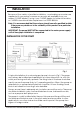
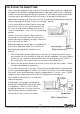
SUCTION LIFT OR GRAVITY FEED The schematic diagrams, figs. 2 and 3, illustrate possible methods of pipework installation. This pump is designed primarily to be gravity fed, that is, drawing water from an above ground pool. However, it is possible to draw water from a sunken pool, providing the suction lift does not exceed the distance specified for your pump. The suction lift i.e. the vertical distance between the water level and the pump should not exceed 7 metres.
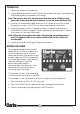
OPERATION 1. Open any valves in the pipeline. 2. If operating the pump for the first time, disconnect the top hose and prime the pump by filling completely with water. Note: The pump is only self- priming when filled with water. Refilling is only necessary if the pump has been drained, or if all the water has been lost. 3. Connect to the power supply and switch on. Water should start to flow through the system. Check for any leaks and repair as necessary. 4.
CARE DURING USE 1. Do not allow the pump to run dry, otherwise the seal between the pump and motor may be damaged. If a leak is noticed at this point, it may indicate that the seal is worn and therefore in need of replacement. Contact your CLARKE dealer, or the Clarke International Service Department for advice. 2. In the event of a blockage, where debris has entered the suction chamber, it can be cleaned out as described under MAINTENANCE. 3.
THE TIMER BATTERY The timer is equiped with a re-chargable battery which should re-charge when the pump is running. Tamper-proof screws are used to secure the top cover requiring a Y-type screwdriver. If one is not available and the battery has failed, take the pump to your Clarke dealer. ENVIRONMENTAL PROTECTION Do not dispose of this product with general household waste. It should be disposed of according to the laws governing Waste Electrical and Electronic Equipment at a recognised disposal facility.
TROUBLESHOOTING PROBLEM CAUSE SOLUTION No mains supply Check fused power supply and replace fuse if necessary (check fuse rating). Check circuit breaker. Impeller seized/blocked. Disconnect pump from mains supply. Investigate cause and clear blockage. Pump does not run. Pump fails to prime. Pump runs but gives poor output. Repair connections/replace hose Air leaks through suction as necessary. hose joints (damaged hose, broken clamp, damaged/ill-fitting gasket) Blocked inlet hose.
TROUBLESHOOTING PROBLEM CAUSE SOLUTION Undue vibration or noise. Excessive flow of water. Decrease flow of water. by adjusting inlet/outlet valves in system. Resistance in inlet pipe caused by obstruction. Check pipe and clean out as necessary. Loose rotating component Return to your dealer for repairs. Installation of pump is unstable. Stop pump and re-position. Air pocket in pump or pipeline. Release drain plug in impeller housing to release air.
PARTS LIST No Description No Description Qty Qty 1 Socket Headed Bolt 6 23 Screw 1 2 Impeller Housing 1 24 Star Washer 1 3 Nut 1 25 Self-tapping Screw 6 4 Flat Washer 1 26 Main Seal 1 5 Washer 1 27 Ball Race 1 6 Impeller 1 28 Key 1 7 O-ring Seal 1 29 Ar mature 1 8 Mounting Frame 1 30 Circlip 1 9 Water Seal 1 31 Ball Race 2 10 Motor Cover 1 32 Tamper-proof Screw 4 11 Socket Headed Bolt 4 33 Control Box Cover 1 12 Motor Stator Assembly 1 34 Plastic Wa
PARTS DIAGRAM SPARE PARTS When requesting spare/replacement parts for these pumps from CLARKE Parts & Service, please quote the prefix ‘ZG’ followed by the model number (SPPT1) and the item number from the parts list/diagram. 14 Parts & Service: 020 8988 7400/E-mail:Parts@clarkeinternational.com or Service@clarkeinternational.
DECLARATION OF CONFORMITY 15 Parts & Service: 020 8988 7400/E-mail:Parts@clarkeinternational.com or Service@clarkeinternational.