Operator's Manual Super 7R DC Edger READ THIS BOOK This book has important information for the use and safe operation of this machine. Failure to read this book prior to operating or attempting any service or maintenance procedure to your Clarke American Sanders machine could result in injury to you or to other personnel; damage to the machine or to other property could occur as well. You must have training in the operation of this machine before using it.
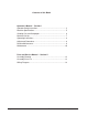
Contents of this Book Operator's Manual - Section I Operator Safety Instructions ......................................................... 3 Machine Specifications ................................................................ 5 Sanding Cuts and Sandpaper .................................................... 6 Machine Set-Up ........................................................................... 7 Operating Instructions ...................................................................
OPERATOR SAFETY INSTRUCTIONS WARNING AVERTISSEMENT ADVERTENCIA DANGER means: Severe bodily injury or death can occur to you or other personnel if the DANGER statements found on this machine or in this Operator's Manual are ignored or are not adhered to. Read and observe all DANGER statements found in this Operator's Manual and on your machine.
DANGER: DANGER: DANGER: Operating partially assembled sanding equipment could result in injury to the operator or bystander and could cause damage to the equipment or to other property. • Do not operate this equipment unless it it fully assembled and all guards, doors and covers are secured. • Keep all fasteners tight. • Keep all adjustments within manufacturers specifications. Moving parts on this sanding equipment can cause injury to the operator or bystanders.
Model Super 7R Specifications Dust Collection Bag Control Switch Work Light Operating Handles Wall Guard Abrasive Wrench Steel Reinforced Molded Rubber Sanding Pad Specifications Model 07125A Electrical Requirements 07126A 115V ~, 60 Hz 230V ~, 50 - 60 Hz 12.0A, 1.3 kW 6.0A, 1.3 kW Storage Case Standard Standard Motor Series Universal Series Universal Abrasive Size 7" x 7/8" Dia. Disc 7" x 7/8" Dia.
SANDING CUTS AND SANDPAPER Initial Cut The purpose of the initial cut is to remove old finish and gross imperfections on the floor surface. A coarse abrasive should be used. If glazing, loading, or burning takes place immediately into an initial cut, select a coarser abrasive. If this should occur during an initial cut, the abrasive has dulled and must be replaced. Final Cuts The purpose of a finishing cut is to remove the scratches produced during the initial cut. Use a fine (60 - 80 grit) grain abrasive.
MACHINE SET-UP This sanding machine is designed to be operated with a remote vacuum dust collection sytem or with the included dust bag. Preparing Remote Vacuum Dust Collection Sytems To prepare the machine for remote vacuum dust collection systems that have a 2" hose end, follow this procedure: 1. Install 2" hose end directly over the exhaust tube. 2. The exhaust tube can be rotated for optimum convenience.
MACHINE SET-UP Cont. Preparing the Machine for Operation 1. Remove screw and abrasive retainer. Center abrasive on pad and secure with abrasive retainer and screw. (Figure 1) 2. Return machine to upright position and tilt machine back on casters until it comes to rest on the exhaust bracket. Machine will be in a reclined position. Do not allow machine to rest on pad especially after use, or compression set may take place within elastomer on pad. This will create a flat spot and bounce during use.
ADJUSTMENT PROCEDURES Leveling To level machine: Grasp caster adjusting screw "A" with an appropriate tool (pliers ect.). Using a similar tool, loosen locknut "B" with a counter clockwise motion. (Figure 4). A Condition - Pad creates ridges on both edges or a "hop" is experienced: Rotate both adjusting screws equal amounts clockwise. Tighten locknuts and test on a piece of plywood. Repeat procedure until condition is corrected. We recommend you not exceed 1/8" rotation for each attempt.
MAINTENANCE CAUTION: Maintenance and repairs performed by unauthorized personnel could result in damage or injury. Maintenance and repairs performed by unauthorized personnel will void your warranty. Failure to perform maintenance at recommended intervals may void warranty. Carbon Brushes Inspect all four brushes every 6 months or 250 hours. Access to the brushes is gained through the front and back motor vent plugs and under both motor covers (figure 5).
Super 7R Edger Section II Parts and Service Manual (70895A) Clarke® American Sanders Super 7R Operator's Manual Page 11
Super 7R Edger Drawing - 11/04 53 2 1 99 97 3 5 96 14 95 14 12 4 37 6 34 98 54 36 35 40 7 7 41 56 8 46 48 9 10 38 49 39 41 50 11 57 58 50 18 16 47 32 63 31 15 17 19 52 62 51 29 64 65 66 67 68 87 65 61 60 47 20 33 69 73 74 21 23 76 24 77 30 70 75 22 25 26 28 33 100 65 71 65 72 75 90 27 29 78 91 92 93 79 80 81 82 83 84 85 Page 12 94 Clarke® American Sanders Super 7R Operator's Manual
Super 7R Edger Parts List - 11/04 Ref# 1 2 3 4 5 6 7 8 9 10 11 12 13 14 15 16 17 18 19 20 21 22 23 24 25 26 27 28 29 30 31 32 33 34 35 36 37 38 39 40 41 46 47 48 49 50 51 52 Part No. 962404 70487A 646302 47394A 302310 302309 306802 43201A 40818A 40055A 962727 962988 980662 Description Screw - #10-24 x 3 ¼ Ft. St. Mach. Plate - Name Plate - Dial Switch - Toggle Cover, Motor Brush R.H. Cover, Motor Brush L.H.
Model Super 7R Edger Wiring Diagram 11/04 Page 14 Clarke® American Sanders Super 7R Operator's Manual
CLARKE PRODUCT SUPPORT BRANCHES U. S. A.
Clarke® American Sanders U. S. Warranty This Clarke American Sanders Industrial/Commercial Product is warranted to be free from defects in materials and workmanship under normal use and service for a period of one year from the date of purchase, when operated and maintained in accordance with Clarke American Sanders's Maintenance and Operations Instructions. This warranty is extended only to the original purchaser for use of the product.