
Owner's manual


3
© Copyright 2012. All rights reserved.
P R E L I M I N A RY
The NSF mark displayed here
will be on all NSF Standard
40, Class 1 certied Fusion
®
systems. The Fusion
®
models
ZF-450, ZF-600 and ZF-800 will
have the mark displayed on the
alarm panel. Systems not NSF
Standard 40, Class 1 certied,
will not display the mark.
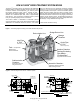
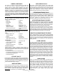
Back-Wash
Recirculation
Sedimentation Chamber
Anaerobic Chamber
Aeration Chamber
Storage Chamber
Effluent
Inflow
1
2
3
4
Figure 3 - Treatment Flow of the Fusion
®
System.
PROCESS DESCRIPTION
1. Sedimentation Chamber
This chamber is designed to physically separate solids
from the incoming water. Scum is the oating material
and sludge is the material that has settled at the bottom.
2. Anaerobic Chamber
This chamber contains a spherical skeleton-type lter
media, 4.3 inch diameter (109 mm). Through bacterial
growth processes on the surface of the lter media,
biological anaerobic treatment thrives while suspended
solids are captured. Furthermore, the microorganisms
in this chamber convert nitrates in the recirculated water
returning from the aerobic chamber to gaseous nitrogen.
The gaseous nitrogen then escapes to the atmosphere.
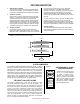
3. Aeration Chamber
The aeration chamber consists of an aerated upper
section and a lter media lower section. The chamber is
lled with hollow, cylindrical lter media 0.6 inch diameter
(15 mm) and 0.55 inches long (14 mm). Biological
treatment takes place on the lter media surface.
Aeration is continuous. Residual suspended solids are
captured by the lter media circulating in this section.
During normal operation, a recirculation line transfers
water back to the sedimentation chamber by way of an air
lift pump.
The lter media in the aeration chamber are backwashed
regularly (twice a day, 5 or 10 minute cycle) by the
backwash system located at the bottom of the chamber.
The accumulated sludge is transferred by an air lift pump
back into the sedimentation chamber for further digestion.
4. Storage Chamber
This chamber is designed to temporarily store treated
water exiting the aeration chamber. This treated water is
ready for discharge.
The complete wastewater treatment system will typically consist of
the Fusion
®
treatment components and a soil absorption eld for nal
disposal of the liquid efuent. Some states or counties may require
the addition of a septic tank before the Fusion
®
to increase the
sedimentation chamber capacity and retain more solids. Please see
Figure 11 for a typical Fusion
®
system. Variations to the typical system
will be made to suit your particular site and system design needs.
Please contact your authorized Fusion
®
installer or maintenance
provider for further information about your system design.
®
Certified to
NSF/ANSI
Standard 40
Class 1
Performance
Designation
Figure 4
NSF STANDARD 40, CLASS 1,
CERTIFICATION MARK
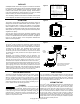
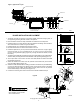
The Fusion
®
treatment unit comes with an electronic, dual-
port blower designed specically for use with this system. The
blower utilizes a linear motor and two diaphragms to generate
the air ow necessary to aerate and recirculate water within the
system. This style of compressor is quieter and more efcient
than traditional rotary vane compressors. Once installed and
adjusted, circuitry within the blower will automatically switch the
unit from normal recirculation mode to backwash mode and back
again when appropriate. In the event of a power outage, the
blower will stop, but a backup battery within the unit will retain
the correct time and backwash settings.
THE FUSION
®
DUAL-PORT BLOWER
SYSTEM COMPONENTS