
Owner's manual


6
© Copyright 2012. All rights reserved.
P R E L I M I N A RY
1. Excavate an area large enough for the Fusion
®
Series unit to be installed. See Figure 8 and Table 3 for the actual dimensions
of the unit. Excavation dimensions are calculated by adding 12-18" (305-457 mm) to the length and width of the Fusion
®
. This
will allow sufcient room for proper backlling.
2. Construct a 6" (152 mm) thick stone pad of either 1/4" - 1/2" (6-13 mm) diameter stone or concrete pad and level to within 1/8" (3 mm).
3.
If the unit is not level, it will cause uneven water ow as well as unbalanced aeration, which will result in
poor performance.
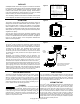
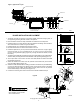
4. Gently lift the unit at all four lifting points with a harness and install it on leveled stone pad (Figure 9).
5. Check unit to make certain it is level by placing a level at several locations on the riser. (riser covers removed) (Figure 9).
1. If groundwater is present, anti-otation measures must be
used to stabilize the unit prior to backlling. Please follow
the procedures in the Anti-otation section to properly
anchor the Fusion
®
.
2. Fill the unit with clean water to the normal operating depth
prior to backlling. Partition walls between chambers are
water-tight and will ll in succession beginning on the inlet
side of the unit. Therefore, it is best to alternate chambers
when lling with water so the unit remains level. Check for
leakage around the unit.
3. If necessary, install riser extensions on the adapter rings
prior to backlling. See Table 1 for number and size of
access opennings. Riser extensions are available for
deeper burial. Make certain risers are sealed properly and
watertight.
4. Apply two beads of silicone fully around
each riser section prior to securing with supplied screws.
5. Install riser covers.
6. Backll with good quality granular soil around the unit that is
free of organic matter, rock, stone, tree roots, or other debris
that could damage the unit.
7. Tamp soil around perimeter of the unit as it is backlled to
stabilize the unit and to reduce settling.
8. Finalize backll with a mounded contour so that surface
water is shed away from the unit. Under no circumstances
should surface water be allowed to accumulate around unit.
9.
MAXIMUM soil burial depth over the unit
is 36 inches (914 mm).
EXCAVATION AND INSTALLATION
BACKFILLING
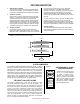
Number aND size of access opeNiNgs iN fusioN
®
series
ZF-450 ZF-600 ZF-800
20" (51 cm) Diameter
0 1 1
24" (61 cm) Diameter
2 2 2
Table 1
COLD WEATHER INSTALLATION
When installing Fusion
®
in cold climates, the designer should
specify insulated lids and risers from the factory. These are
available as an option to the standard lids and risers. In addition,
the blower must be protected from snow drifts by installing it
either inside a garage, home, basement, crawlspace or riser. If
installed in a riser, the blower must be protected from inundation
and must have a vent pipe installed to above the maximum
snow depth with a 180 degree angle at the end to prevent snow
and water entry. Also, the top and sides of the Fusion
®
must be
insulated with insulation sheeting or other means to provide a
minimum insulation value of R-8. Please contact the factory for
further information.
ANTI-FLOTATION PROCEDURES
It is necessary to anchor the Fusion
®
in high ground water
conditions to prevent otation. If groundwater rises above the
rock or concrete pad that the Fusion
®
sits on, anchoring is
required. Please consult a design engineer, soil scientist or other
qualied individual to determine high groundwater conditions.
1. Follow the procedures outlined in the Excavation and
Installation Section items 1-5 to properly prepare and level
the Fusion excavation.
2. Follow the procedures outlined in the Backlling Section
items 1-4 to properly ll the Fusion
®
with water and add
risers if needed.
3. Refer to Figure 10, Anchoring Schematic to determine
the minimum amount of backll to be placed around the
Fusion
®
in the excavation. Tamp the ll to prevent settling.
4. Refer to Table 3, Concrete Anchoring Dimensions to
determine the amount of concrete needed for the concrete
anchor collar that is poured around the entire circumference
of the Fusion
®
. Pour concrete to the specied dimensions
to fully engage the mid-seam of the Fusion
®
, which will
anchor it once the concrete cures. Make certain to pour
the concrete in a manor to minimize trapped air within
the concrete. Agitating or lightly mixing the concrete with
a metal rod or other similar device once poured will help
release trapped air.
5. Allow the concrete to harden before nal backlling.
6. Complete the procedures outlined in the Backlling Section,
items 5-8.
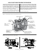
I
E
H
OUTLET
INLET
W
L
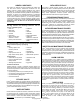
1) DIMENSIONS "I" AND "E" ARE TO THE BOTTOM
OF THE INLET/OUTLET PIPE.
2) THE OVERALL HEIGHT DIMENSION "H" IS TO THE
TOP OF THE NARROW ADAPTER RING, NOT THE RISER LID.
NOTES:
3) A RISER COVER COMES STANDARD. ADDITIONAL RISERS ARE
PURCHASED SEPERATELY.
Figure 8- Dimensions
Table 2
FUSION
®
DIMENSIONS
SYSTEM L W H I E
Fusion
®
450 7'-1" (2.2 m) 3'-8" (1.1 m) 5'-2" (1.6 m) 4'-4" (1.3 m) 3'-10" (1.2 m)
Fusion
®
600 8' (2.4 m) 4'-1" (1.2 m) 5'-6" (1.7 m) 4'-8" (1.4 m) 4'-2" (1.3 m)
Fusion
®
800 8'-3" (2.5 m) 4'-8" (1.4 m) 6'-2" (1.9 m) 5'-4" (1.6 m) 4'-10" (1.5 m)
sk2624