
Owner's manual


8
© Copyright 2012. All rights reserved.
P R E L I M I N A RY
WARNING!
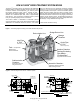
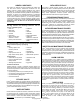
TO DRAIN FIELD
SEWER LINE
FUSION CONTROL PANEL
BLOWER
RISER AND LID
FUSION
OPTIONAL SEPTIC TANK INSTALLATION
MAY BE REQUIRED BY LOCAL
OR STATE REGULATIONS
AIR LINE
CLEAN - OUT
Figure 11, Typical Fusion
®
Layout
sk2650
1. The blower must be connected to a grounded, metallic, permanent wiring system, or
an equipment-grounding terminal or lead on the product.
2. Place the blower where it is easily accessible for maintenance and inspection.
3. Install the blower in an area where it will be protected from damage and inundation.
Also make certain the location has good ventilation.
4. Install the blower on a foundation that is level and solid.
5. Excavate trenches for two air lines from blower to the unit.
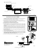
6. Install two separate 1/2" (13 mm) air lines from the blower to the unit. Length of piping
must be less than 17' (5 m). If distances from 17' (5 m) to 33' (10 m) are required,
use 3/4" (19 mm) diameter piping (Figure 12). If longer air lines are needed, consult
the factory.
7. The blower is provided with two discharge ports. The blower label is color-coded with the
aeration outlet port being BLUE and the backwash outlet port being RED (Figure 12).
8. The air port inlets on the Fusion
®
are also color-coded, BLUE for aeration and RED
for backwash (Figure12).
9. Attach the barbed end of each PVC tee (included in the blower box) to the blower
using the rubber elbows (Figure 12).
10. Attach the small diameter black air tubing (included in the blower box) to barbed tting
on PVC tee. Black air tubing and blower power cord should be routed to the alarm
panel through conduit. Attach the two black air tubing lines to the two air pressure
sensor barbed ttings in the alarm panel (Figure 12).
11. Connect the remaining end of each PVC tee to the airlines installed in Step 6.
!
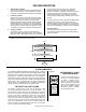
RISER CONFIGURATION
DECORATIVE ROCK CONFIGURATION
INTERIOR CONFIGURATION
RUBBER
ELBOWS
POWER
CORD
BLUE AIR
LINE
RED AIR
LINE
CONDUIT TO
PANEL
AIR LINE
TO PANEL
ADAPTER
BLOWER
AIR LINE
TO PANEL
RED AIR
LINE
BLUE AIR
LINE
BLOWER INSTALLATION AND PLACEMENT
Figure 12
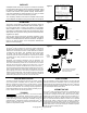
TO PREVENT ELECTRICAL SHOCK FROM
BACK-SIPHONING, LOCATE THE PUMP
ABOVE THE WATER LEVEL.
sk2639