
Owner's manual


9
© Copyright 2012. All rights reserved.
P R E L I M I N A RY
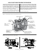
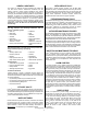
There are two aeration systems provided within the aeration
chamber: normal aeration and backwash. Valves (1 and 3) are
set at 50%. Observe the air ow on each side of the unit to verify
equal ow. If there is an obvious discrepancy in air ow between
the two sides, adjust the valves (1 and 3) so that the ow is equal.
Figure 13- Aeration Flow Adjustment
1. Connect house sewer pipe or septic tank outlet, if
required, to the unit inlet. Make certain only household
waste enters the unit (no foundation drains, gutter
drains, oor drains, etc.).
2. Connect the outlet pipe to the outlet of the unit.
PIPING INSTALLATION
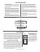
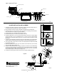
HIGH WATER ALARM FLOAT INSTALLATION
The Fusion
®
alarm panel assembly includes a high water
alarm oat switch that is used to monitor the liquid level in
the Fusion
®
unit. The switch should be tethered to one of
the gray, vertical air lines in the aeration chamber. With
a 3" (76 mm) tether length, the cord should pass through
the opening in the partition wall between the aeration and
anaerobic chamber and allow the oat to hang in the outlet
bafe of the anaerobic chamber.
1. The oat switch should be tethered to one of the gray,
vertical pipes in the aeration chamber. When the oat
is in the horizontal position, the cord should be at
least 1" (25 mm) below the top of the partition wall
opening in the anaerobic chamber bafe.
2. Place the cord into the clamp and secure to gray aeration
pipe. NOTE: Do not install the cord under the clamp.
3. Position the oat with a 3" (76 mm) tether.
4. Tighten the clamp with a screwdriver. Be careful not
to overtighten as this may cause damage to the plastic
clamp.
5. Make sure the oat cord is not allowed to touch the
excess clamp band during operation as this may
cause damage to the cord.
6. The oat switch cord should be installed in an electrical
conduit connecting the alarm panel to the Fusion
®
unit.
The electrical conduit must be rated for burial, and should
be properly sealed to prevent gases from entering the
alarm panel.
7. A ½" (13 mm) bulkhead tting (supplied by others)
should be used to connect the electrical conduit to the
Fusion
®
unit. A hole must be drilled through the wall of
the Fusion
®
unit between the red and blue bulkhead
ttings to facilitate this connection.
8. Please be certain that the bulkhead tting for the
electrical conduit forms a watertight connection with the
FRP wall of the Fusion
®
unit.
9. Electrical conduit from the Fusion
®
unit to the alarm
panel can be buried in the same trench as the air lines.
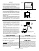
10. The control switch can be wired directly into the alarm
panel. See Figure 7.
1.
All electrical installations must follow
the National Electrical Code and/or your local/state
electrical codes.
2. The blower should be directly wired into the alarm panel.
The alarm panel must be located in a dry location that
is accessible for maintenance. Please see Figure 7 and the
wiring diagram and instructions enclosed with the alarm panel.
3. Make certain the timer within the control panel is set to
the proper time. The timer unit display should be set to
10 hrs. and the timer dial needle set to 3.6 for 36 hours.
This will activate an alarm if the blower doesn't go into
backwash cycle within a 36-hour time frame.
ELECTRICAL CONNECTIONS
START UP
An installation and start-up check list (CL0057)
is furnished with the information package in the blower box.
Please use this as a guide and ll out all sections and return
to your distributor.
Valve Legend:
1. Aeration Blue 3. Backwash Red
2. Recirculation Gray 4. Sludge transfer Gray