
Instruction Manual

NOTICE TO INSTALLER: Instructions must remain with installation.
© Copyright 2011. All rights reserved.
READ ALL INSTRUCTIONS BEFORE INSTALLING - ALL APPLICATIONS
Make sure the pump electrical supply circuit is equipped with fuses or circuit breakers of proper capacity. A separate branch circuit is recommended,
sized according to the National Electrical Code for the current shown on the pump name plate.
FOR YOUR PROTECTION ALWAYS DISCONNECT PUMP FROM ITS POWER SOURCE BEFORE HANDLING. Single phase pumps are supplied
with a 3-prong grounded plug to help protect you against the possibility of electrical shock.
DO NOT UNDER ANY CIRCUMSTANCES REMOVE THE GROUND PIN. The 3-prong plug must be inserted into a mating 3-prong grounded recep-
tacle. If the installation does not have such a receptacle, it must be changed to the proper type, wired and grounded in accordance with the National Electrical Code and
all applicable local codes and ordinances.
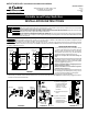
FIGURE 1
CORDS SECURED
"ON"
"OFF"
LEVEL
LEVEL
TO DISCHARGE
PIPE
RANGE
PUMPING
FLOAT
CLAMPS
THE "ON" LEVEL IS
APPROXIMATELY 4"
ABOVE MOUNTING
LOCATION
THE "OFF" LEVEL IS
APPROXIMATELY 4"
BELOW MOUNTING
LOCATION
MECHANICAL FLOAT SWITCH
10-1964, 10-1965, 10-1966, 10-1967
CORDS SECURED
"ON"
"OFF"
LEVEL
LEVEL
TO DISCHARGE
PIPE
FLOAT
CLAMPS
NARROW ANGLE
FLOAT SWITCHES
RANGE
PUMPING
SK308B
Clarus Environmental 10-0229, 10-0230, 10-1209, 10-1210, 10-1964, 10-1965, 10-1966 and 10-1967 Variable Level Pump Switches are designed for use with
the appropriate voltage and horsepower, nonautomatic, single phase, Clarus Environmental pumps.
Use 10-0229, 10-1209, 10-1964 and 10-1966 for 115V and 10-0230, 10-1210, 10-1965 and 10-1967 for 230V. All can be used as a control switch for a magnetic
or combination starter. Maximum temperature must not exceed 140°F. NOTE: UL Recognized and CSA approved. NOTE: Consult Clarus Environmental for controlling units over
1½ HP with a variable level pump switch.
INSTALLATION INSTRUCTIONS
1. Decide the desired pumping range for your installation. (See Fig.
1.) Secure the oat cable clamps to the discharge pipe at the
distance you desire. (See clamp detail in Fig. 6 on next page).
The oat labeled “TOP” must be on top. (The cable clamps are
releasable, which permits readjustment and removal.)
NOTICE: Do not adjust “Off’’ Level below discharge on
pump.
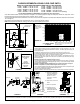
2. Insert the piggyback plug from the switches into a standard grounded
outlet of proper voltage. For automatic operation plug the pump
directly into the piggyback plug. (Pump can be manually operated
by bypassing piggyback plug.) See Fig. 2.
NOTICE: For installation utilizing a watertight junction box or
similar connections, see Figure 3.
NOTICE: For installation as a control switch for magnetic or
combination starter, see Figure 4.
3. Securely tape or clamp both piggyback switch cord and pump cord
to the discharge pipe, clear of oat operation. (See Fig. 1.) Excess
cord should be coiled and fastened to the discharge pipe.
4. Clean basin free of debris after installation.
5. Check and test your installation. Fill basin with water and allow pump to cycle to insure proper range and operation. NOTICE: For installation utilizing a Piggyback Float Switch
connection use Clarus Environmental Qwik-Box.
FIGURE 2 FIGURE 3
FIGURE 4
A) Remove (cut) Piggyback
Plug from Variable Level
Pump Switch. Remove
approx. 3½” of cord
jacket and 1” insulation
from wires.
B) Wire switch into circuit as
shown.
C) Return to Instructions.
D) Installation must be in
agreement with the
National Electrical Code
and all local codes.
SK308C
PUMP PLUG
SWITCH PLUG
AUTOMATIC
OPERATION
MANUAL
OPERATION
SK308A
VARIABLE
LEVEL
PUMP
SWITCHES
SK378B
VARIABLE
LEVEL
PUMP
SWITCHES
Variable Level Pump Switches
SECTION: C6.00.043
CL0117
1111
Supersedes
New
3649 Cane Run Road
.
Louisville, KY 40211-1961
877
-
244
-
9340
.
Fax: 877
-
414
-
4316
www.clarusenvironmental.com
®
®
INSTALLATION INSTRUCTIONS