Captain Pressure Governor Universal Version With Trim Control Technology Leaders for Emergency Vehicles
Installation and Technical Manual Pressure Governor for Electronic Engines V6.0 Contents Operation Section Overview ....................................................................................2-3 v6.0 Features ............................................................................... 4 Operation ..................................................................................5-8 Troubleshooting / Diagnostics Diagnostics ..........................................................................
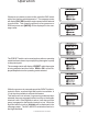
Overview Electronic Engine Pressure Governor The Class1 Pressure Governor is designed to maintain a selected pump pressure or engine speed setting. This unit will work with electronically controlled engines that accept a variable analog voltage signal (0-5 VDC) or a Pulse Width Modulated Signal (PWM 12%-87% at 400 Hz) as a remote accelerator (throttle) signal. Included in the package The standard governor control is shipped with the following components.
Overview Preset Mode Pressing the PRESET switch in either mode will control the engine to attain the preset RPM or pump pressure programmed in governor memory. If there is more than 10 PSI pressure on the pump, the RPM Preset is disabled and the Message Center will display DISABLED. High Idle Mode An input is available to bring the engine speed to a PRESET RPM (High Idle) from a remotely mounted switch. While operating in this mode, the display will show HIGHIDLE.
v6 . 0 Features Version Display While the governor is at idle and [MODE] is being displayed, if the IDLE switch is depressed for 7 seconds, the message center will scroll through the version number, governor settings and I/O voltage. When the sequence is complete, the display will return to [MODE] and normal operation is available. PSI Enable The pressure governor will not control pressure until a discharge pressure of 70 PSI is attained. It will act as a throttle until this pressure point is achieved.
Operation IDLE REQ When the governor is initially powered up, neither the RPM nor the PRESSURE LED will be illuminated. If the IDLE Switch is held on prior to power being applied, the information will remain in the message center as long the IDLE Switch is depressed. V 6.0b444 At this point, the operator must select an operating mode with the MODE switch before the governor will operate.
Operation NO-INTLK If you attempt to select pressure mode, NO-INTLK will be displayed when the MODE switch is pressed and the governor will revert to RPM mode and RPM will be displayed. RPM The governor will respond to increase and decrease commands from the INC and DEC switches within the operating capabilities of the engine. When the INC switch is pressed, INCREASE is displayed in the message center. INCREASE DECREASE When the DEC switch is pressed, DECREASE is displayed.
Operation IDLE REQ Whenever you desire to return to idle, press the IDLE switch with a firm positive switch depression. The message center will display IDLE REQ and the engine speed will be reduced to normal idle. This clears the governor of any pressure or RPM set points and [MODE] will be displayed in the message center. [MODE] -PRESET- The PRESET switch can be used anytime after an operating mode has been chosen to promptly bring the engine or pump to the preset point.
Operation PSI When operating in pressure mode, once the pump pressure exceeds 70 PSI, the governor will monitor the pump discharge pressure and respond to changes in pressure by modulating engine/pump speed. If the discharge pressure drops and the governor is unable to regain pressure within 4 seconds, the Message Center will flash -INTAKE- to indicate an insufficient water supply the governor will then reduce speed to the point that the pressure was last achieved.
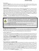
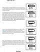
Diagnostics Class1 Uni-Governor Quick Tests Operation description: The governor is simply a Throttle Position Sensor (TPS) for the Engine Control Module (ECM). It sends a varying voltage signal, or for Caterpillar Engines (CAT) a Pulse Width Modulated (PWM) signal to the ECM at the remote throttle signal input. When operating in pressure (PSI) mode, the governor modulates the output signal to maintain a specific input voltage from its pressure transducer.
Passwords: There are several diagnostic modes available in the governor. Access is provided by entering a password that uses the INC and IDLE switches in a specific sequence. The Message Center must display [MODE] prior to entering any password. Governor Self Test: The Self Test password is: IDLE INC IDLE INC IDLE INC IDLE INC This test is capable of determining if there is a problem with the governor that replacement of the governor display will correct.
Contents Page Problem specific tests: 1 Governor does not power up, Message Center is blank THROTTLE READY led and/or PUMP ENGAGED LEDs may be illuminated.
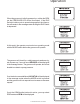
1 Governor does not power up, Message Center is blank Check for power at pin 1 of the 4 pin connector and ground at pin 2 with a voltmeter across pin 1 (red lead, power) and pin 2 (black lead, ground). Check that the terminals are fully inserted into the connector, the orange wedge lock is inserted properly and the weather seal is in place and not distorted. If Power and Ground are present and the governor Message Center is still blank then the problem is internal and the governor should be replaced.
3 Governor Message Center displays SENSOR The governor will display SENSOR whenever the transducer input is less than 0.3 VDC. This input is at pin 7 of the governor 12 pin connector. You can measure this voltage in either of two ways. A voltmeter back probing pin 7 or on the governor Message Center. Enter the password: INC IDLE IDLE IDLE IDLE IDLE INC IDLE The message center will display XDC=x.xV where x.x is the voltage to one decimal place that is read at pin 7.
5 Governor changes engine RPM but will search or hunt (oscillate) when in pressure mode There are three programmable parameters that can fine tune governor operation. These are RAMP, GAIN and SENSITIVITY. To enter the Menu System: With [MODE] showing in the Message Center, Press and hold the IDLE and PRESET switches. While still holding these, press MODE. This puts you into the MENU system where the RAMP, GAIN and SENS settings can be changed. Scroll through the 3 parameters using the MODE switch.
6 Governor overshoots the PRESET PSI and then oscillates with increasingly wider swings This can be caused by GAIN being set too high or SENSitivity set too low. In a few cases, the PRESET is just set too high. PRESET is intended to allow very fast initial response to get up and pumping and a normal setting would be around 125 PSI. Once the apparatus is pumping water, the pressure setpoint should be manually invoked with the INC or DEC switches.
9 One or more switches are inoperative This condition can be diagnosed with the self test IDLE INC IDLE INC IDLE INC IDLE INC If you cannot enter the selftest, then one of the switches is shorted to ground and the governor must be replaced. If you can enter the selftest, when the Message Center displays X X X 3 - 5 X X Each time you press a switch a letter will be displayed in position 2, just before the 3.
13 Message Center display garbled or dim This is an internal component of the governor and there is no field repair to correct a dim display. The governor should be replaced. Contact Class1 at 1 800 533 3569 14 CAVITATE is displayed in the Message Center This indicates that the governor has performed a cavitation check and the transducer signal remained below 25 psi for at least 5 seconds. If the apparatus was run away from water then this is the case. If not, the transducer circuit needs to be checked.
Self Test POS-0 OEM Interlock POS-1 PTO Interlock POS-2 Switch Panel POS-3 Analog Type POS-4 PWM Type POS-5 Transducer POS-6 High Idle Input POS-7 Internal Relay TEST SETUP The apparatus should have the engine running at idle with the transmission in neutral, the parking brake applied and the pump should not be engaged. POS-7 POS-6 POS-5 POS-4 POS-3 POS-2 POS-1 x x x x x x x x POS-0 Monitor the Message Center and note what is displayed.
Installation Installation Control Module The control module requires a rectangular cutout as shown. The module is watertight and may be mounted in any location on the operators panel. 02817,1*+2/(6$1' &87287',0(16,216 Pressure Transducer Locate the pressure transducer where it can read pump discharge pressure without turbulence. A ‘tee’ at the Master Discharge Gauge would be a good location, this should also reduce vibration to the transducer.
-4 & -12 Connector B A Connector A 1 2 3 4 System Power System Ground Plug Plug 12 VDC Ground NC NC Connector B 1 2 3 4 5 6 7 8 9 10 11 12 5 VDC input Throttle Interlock High Idle CAT ID Input Transducer Ground Transducer Voltage Transducer IN Analog Out Signal Ground Pump Engaged Interlock Delay Relay Common (30) Delay Relay NO (87) DT06-4S INPUT INPUT ----------------DT06-12S 5 VDC 12VDC 12 VDC 12 VDC XDucer Ground XDucer 5 VDC Xducer Signal Control Signal Ground 12 VDC Enable Input Enable Output
PSI Transducer Pressure Transducer cable and connector.
Wiring &211(&725'(876&+ '76$ 326:,5('(6&5,37,21 9'& 2(0,17(5/2&.9'& +,*+,'/(9'& &$7,17(5/2&.9'& 75$16'8&(5*5281' 75$16'8&(56833/< 75$16'8&(56,*1$/ &21752/6,*1$/ 6,*1$/*5281' 372,17(5/2&.9'& (1$%/(6833/< (1$%/(287387 &211(&725'(876&+ '76 326:,5('(6&5,37,21 5('9'& %/$&.*5281' 3/8* 3/8* &2113$&.
Wiring Power and Ground It is imperative that the Class1 Pressure Governor be supplied power and ground from the same source as the engine Electronic Control Module. This is the only configuration that will assure reliable operation. Terminal A-1 This is the Governor power input 12/24 VDC. Terminal A-2 This is the Governor ground input. Interlocks There are two (2) 12 VDC interlocks that must be supplied to the governor for operation.
24 Wire Color RED Black Plug Plug DT06-12S Sockets Wire Color Red White White Brown Black Red White Yellow Black White Orange Blue Position 1 2 3 4 Connector Terminal Position 1 2 3 4 5 6 7 8 9 10 11 12 Description + 5 VDC OEM Interlock High Idle NC Sensor Ground Sensor Voltage Sensor Signal Control Signal Throttle Return PTO Interlock Enable Input Enable Output Description + 12 VDC Ground NC NC ECU Power Ground +5 VDC Signal A Black B Red C White Transd Conne Pump Engage Pump Engaged C12-10
ISM Wiring Position 1 2 3 4 5 6 7 8 9 10 11 12 Connector Terminal Position 1 2 3 4 Connector Terminal Wire Color Red White White Brown Black Red White Yellow Black White Orange Blue DT06-12S Sockets Wire Color RED Black Plug Plug DT06-4S Sockets ECU Power Cummins ISM Wiring A-21 Remote Throttle A-48 +5VDC Control Signal C12- 8 A-09 Switch Common Reference Voltage C12-1 C12-11 A-49 Throttle Return Delay Rly 30 A-43 Remote Thottle ON/OFF OEM Interlocks FAST IDLE High Idle Switch C12-12
26 Wire Color Description RED + 12 VDC Black Ground Plug NC ECU Power Plug NC Position 1 2 3 4 5 6 7 8 9 10 11 12 Wire Color Red White White Brown Black Red White Yellow Black White Orange Blue C4-2 Ground CAT ID C12-4 12 VDC C4-1 Sensor Ground C12-5 Sensor Voltage C12-6 Sensor Signal C12-7 Ground +5 VDC Signal 12 VDC Pump Engaged Pump Engaged C12-10 FAST IDLE Any questions should be directed to Class1 Support at 1-800-533-3569 Transducer Connector OEM Interlocks Throttle Ready A Black B Re
Navistar Wiring Wire Color RED Black Plug Plug Connector DT06-4S Terminal Sockets Position 1 2 3 4 Wire Color Red White White Brown Black Red White Yellow Black White Orange Blue Description + 12 VDC Ground NC NC Description 97 DD OEM Interlock High Idle CAT ID Sensor Ground Sensor Voltage Sensor Signal Control Signal 97 HM PTO Interlock Enable Input Enable Output Connector DT06-12S Terminal Sockets Position 1 2 3 4 5 6 7 8 9 10 11 12 Navistar Circuit ECM Pin 97DF Switch Voltage 12 VDC 1 Amp 97CC Var
28 Wire Color RED Black Plug Plug Position 1 2 3 4 5 6 7 8 9 10 11 12 Wire Color Red White White Brown Black Red White Yellow Black White Orange Blue Connector DT06-12S Terminal Sockets Position 1 2 3 4 Connector DT06-4S Terminal Sockets 525 Ground Ground +5 VDC Signal Transducer Connector Pump Engaged Pump Engaged C12-10 Sensor Ground C12-5 Sensor Voltage C12-6 Sensor Signal C12-7 Throttle Ready Throttle Ready C12-2 OEM Interlocks FAST IDLE A Black B Red C White High Idle Switch Opposite
Mack Wiring Connector Terminal DT06-4S Sockets DT06-12S Sockets Wire Color RED Black Plug Plug Connector Terminal Wire Color Red White White Brown Black Red White Yellow Black White Orange Blue Position 1 2 3 4 Position 1 2 3 4 5 6 7 8 9 10 11 12 Description + 12 VDC Ground NC NC Description + 5 VDC OEM Interlock High Idle NC Sensor Ground Sensor Voltage Sensor Signal Control Signal Throttle Return PTO Interlock Enable Input Enable Output ECU Power Mack Governor Wiring Pressure Governor Mack ECM
30 DT06-12S Sockets Wire Color Red White White Brown Black Red White Yellow Black White Orange Blue Connector Terminal Position 1 2 3 4 5 6 7 8 9 10 11 12 Description + 5 VDC OEM Interlock High Idle NC Sensor Ground Sensor Voltage Sensor Signal Control Signal Throttle Return PTO Interlock Enable Input Enable Output Description + 12 VDC Ground NC NC ECU Power High Idle C12-3 C12-12 C12-11 Sensor Ground C12-5 Sensor Voltage C12-6 Sensor Signal C12-7 Pump Engaged C12-10 Throttle Ready C12-2 4-2 Gr
Engine ECM Special Programming Considerations for the engine Some Engine Manufacturer’s Electronic Engine Control Module (ECM) must be programmed for remote PTO or remote Throttle operation. Refer to the appropriate Engine Manual for details. If available, the engine should operate in VSG mode when pumping. The pressure governor can be combined with a Class1 Engine Status Center or ENFO III to provide the pump operator with necessary engine information in a matching style display.
Preset Programming Changing the preset RPM or Pressure Holding the PRESET switch as the first function after the governor Power On Cycle accesses the governor PRESET programming function. Apply power to the controller and hold the preset switch until the display indicates PRESET, then release the switch (approx. 10 seconds). Typically , the RPM Preset is an engine speed that either enhances alternator output or provides good pump priming ability.
Engine Type Programming Selecting Engine Type The engine code at powerup should reflect the engine type of the apparatus. If it becomes necessary to change the engine type, a password can be entered to allow engine selection. With [MODE} showing in the message Center, enter the following keypress sequence: IDLE INC INC IDLE IDLE INC IDLE INC The Message Center will display ENG= ??? Select the correct engine type by scrolling through the options using the INC or DEC switches.
Parameter Programming Programmable Parameters These adjustable settings allow the governor to better match the engine/PTO/pump configuration of the apparatus. Press and hold the IDLE and PRESET switches, then press the MODE switch (All three depressed simultaneously). The message center will show -MENUpress the MODE switch. This will scroll through the three menu options. SET RAMP SET SENS SET GAIN SET TRIM When the option that you want to change is displayed, press the INC switch to select it.
Miscellaneous It is essential that the governor be powered at the same time as the engine ECM and that the control signal does not drop out when the engine is started. This signal can be checked at the 12 way connector terminal 8 with a voltmeter. Valid signals for idle are 0.6• VDC and higher, for maximum throttle 3.6 to 4.2 VDC. The governor must have a throttle interlock (12 VDC) signal at terminal 12-2 in order to operate as a throttle or to act on a fast idle input (12 VDC) at terminal 12-3.
Notes The f irst time that the governor is powered up on a vehicle, the Message Center will display ENG? Use the INC and DEC switches to find the proper engine and then press PRESET to save. For all engines except CAT, the control signal is an analog voltage that is software controlled for minimum and maximum output. There is a hardware minimum of 700 mV for idle and 4.2 V for maximum throttle . If the signal is present and varies with the INC/DEC switches, it is functioning. CAT uses a PWM signal.
Gauges Flowmeters Electronic Controls Plumbing Components …And More 607 N.W. 27th Avenue Ocala, Florida 34475 Phone 352‐629‐5020 FAX http://www.class1.