
software v 6 00


2
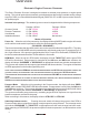
Electronic Engine Pressure Governor
The Class1 Pressure Governor is designed to maintain a selected pump pressure or engine speed
setting. This unit will work with electronically controlled engines that accept a variable analog voltage
signal (0-5 VDC) or a Pulse Width Modulated Signal (PWM 12%-87% at 400 Hz) as a remote accelera-
tor (throttle) signal.
Included in the package The standard governor control is shipped with the following components.
Package 105244 Package 105246
Governor Control C1-PN 107396 107269
Pressure Transducer C1-PN 100581 100581
User Manual C1-PN 107490 107490
Installation Harness C1-PN 105247 Not Included
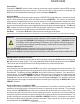
Modes of Operation
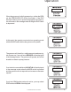
Power On When the unit is first powered up, the display will show [MODE] and the engine will remain
at idle until the mode switch is pressed to select the desired operating mode
(PSI MODE or RPM MODE).
There is an internal relay that should be used to turn on the remote throttle at the engine ECU. This relay
will not energize until the MODE switch is pressed and a valid throttle ready input is present at Pin 2 of
the 12 pin connector. If the pump is engaged and the OK to Pump LED is illuminated, PRESSURE will
be the first mode selected otherwise Throttle will be the first mode.
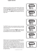
RPM Mode When the unit is in RPM mode, the display will read “THROTTLE” and the green RPM
LED will be illuminated. Engine speed is controlled by the INCrease and DECrease switches, the
display will indicate “INCREASE” or “DECREASE” as appropriate when these switches are depressed.
The governor will maintain the last output signal attained with these switches. The engine will maintain
an RPM appropriate for the throttle signal being sent.
NOTE: IF WHILE OPERATING IN RPM MODE THE PRESSURE INCREASES MORE THAN 50 PSI FROM THE PRESSURE LOGGED AT THE
LAST
SWITCH PRESS, THE GOVERNOR WILL LIMIT THE PRESSURE INCREASE TO NO MORE THAN A 50 PSI DIFFERENTIAL.
THE GOVERNOR MAY REDUCE ENGINE RPM TO ACHIEVE THIS AND THE MESSAGE PSI LIMIT WILL BE DISPLAYED IN THE MESSAGE
CENTER
.
NOTE: THE GOVERNOR WILL NOT ATTEMPT TO REGULATE PRESSURE IN THIS MODE, ONLY LIMIT THE DIFFERENTIAL PRESSURE TO
50 PSI FROM THE PRESSURE PRESENT WHEN THE LAST SWITCH WAS PRESSED.
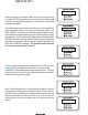
Pressure Mode When the unit is operating in the Pressure mode, the display will show “PRES-
SURE” and the amber PRESSURE LED will be illuminated. Pump pressure is set by using the INCrease
and DECrease switches. The governor will attempt to maintain the last pressure achieved with these
switches. The display will indicate “INCREASE” or “DECREASE” as appropriate.
The governor maintains pump pressure by controlling engine RPM in response to a signal from the
pressure transducer mounted on the pump.
When controlling in this manner, the display will show CTRL DEC or CTRL INC.
Switching between modes Pressing the mode switch will change the governor from RPM to
Pressure mode without a significant change in engine speed or pump pressure. The message center
will indicate “PRESSURE” or “THROTTLE” as appropriate once the mode change has been made.
When switching to PRESSURE, the pressure setpoint is whatever pressure is on the transducer at the
change.
Overview