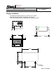
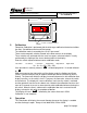
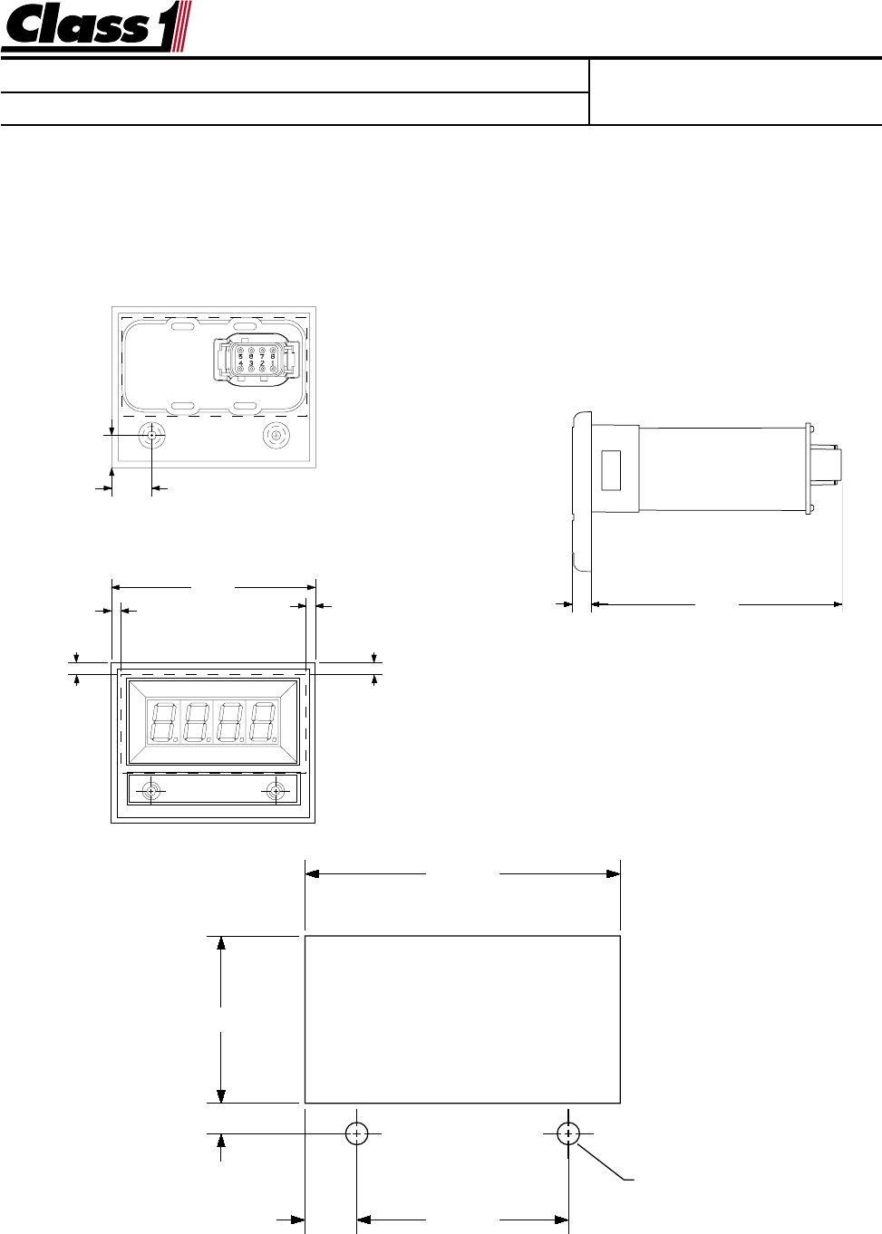
Engineering Standards Name Digital Flowmeter Information Identifier Installation and Calibration Information Engineering Standard Number C1-102046-A Display Installation The flowmeter display mounts in a 2.84” by 1.51” cutout. Overall area necessary for installation is 2.5” by 3.2”. Two 0.201 diameter holes are provided for mounting screws. 0.496" 0.612" 3.125" 0.285" 0.142" 0.142" 0.182" 3.832" 0.182" 2.840" 1.510 .277 Ø 0.201" (2) HOLES .470 1.
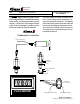
Engineering Standards Name Digital Flowmeter Information Identifier Engineering Standard Number C1-102046-A Saddle Clamp Installation The Saddle clamp should be mounted on the pump discharge pipe in an area of laminar flow. Select a location with as long a straight run as possible. Avoid mounting immediately after an elbow, gate or increase in pipe size (Any thing that would cause turbulence). Allow a straight run of at least 6 pipe diameters after an elbow. Cut a 1.
Engineering Standards Name Engineering Standard Number Digital Flowmeter Information C1-102046-A Identifier Increase/Decrease in pipe size The transmitter can be placed after an increase in pipe diameter, never after a decrease. Class1 flexible hose can greatly assist in reducing the number of elbows and amount of turbulence between the pump and discharge pipe. Wiring The Flowminder system comes with a wiring harness that connects the transmitter to the display.
Engineering Standards Name Identifier Digital Flowmeter Information Engineering Standard Number C1-102046-A Operation The flowmeter displays the current flow rate whenever the display has power and the discharge is open. Range is 0 to 9995 GPM, LPM or IGPM as calibrated. Totalizer The display includes a totalizer function that displays the total amount of water that has been flowed since the unit was turned on. This feature is enabled by grounding terminal number eight (8) of the display connector.
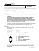
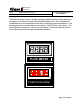
Engineering Standards Engineering Standard Number Name Digital Flowmeter Information Identifier Installation and Calibration Information C1-102046-A 3.125" 2.462" Location of magnetic switches 5. Calibration Flowmeter Calibration is performed with the discharge stabilized at the desired calibration flow. (Smoothbore nozzle and Pitot gauge) The calibration mode is entered by the use of a “password”. There are two magnetic switches located at the lower corners of the display.
Engineering Standards Name Engineering Standard Number Digital Flowmeter Information C1-102046-A Identifier The Class1 digital flowmeter system comes with the digital display, a paddlewheel transmitter and a connecting harness (specify length). A method of mounting the transmitter to the discharge is needed, call for options and specify the pipe diameter. The flow display includes a totalizer function. A momentary switch (optional) is required to operate this feature.
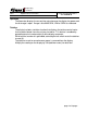
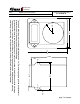
Engineering Standards Engineering Standard Number Digital Flowmeter Information Name C1-102046-A Identifier R 1.325" 3.750" 5.000" .683 3.564" 2.750 .037 R.370 The Value Series flowmeter uses the digital display and a 2-1/2” pressure gauge to give the pump operator information on both flow and pressure for the discharge. A stainless steel bezel is available that can have insets color coded to identify the associated discharge.
Engineering Standards Name Digital Flowmeter Information Engineering Standard Number C1-102046-A Identifier The flowmeter Super System is designed using the digital flowmeter and the digital pressure gauge. Each piece uses the standard digital display cutout. The only additional consideration from the standard flowmeter is for mounting the pressure transducer. This should generally be mounted after the valve and is a 1/4 NPT fitting.
Engineering Standards Name Identifier Digital Flowmeter Information Engineering Standard Number C1-102046-A Enhance your Flowminder Installation The Digital Flow Display is also available in a plain black wrapper that will install into an existing conventional Flowminder cutout on the pump panel. Call Class1 at 1-800-533-3569 and ask for details.