
Owner's manual

page 3 of 9 pages
Engineering
Standards
Name
Identifier
Engineering Standard Number
C1-102046-A
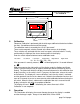
Digital Flowmeter Information
Electrical
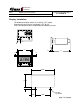
The Flowmeter Display is connected to the OEM harness with a Deutsch 8 pin
mini-connector.
Mating Connector: DTM06-08S
Locking Wedge WM-8S
Mating Terminal: 0462-201-20141 20 gauge socket
Terminal Assignments: 1 N/C (no connection)
2 N/C
3 N/C
4 Display Power (Ignition 12 VDC)
5 System Ground
6 N/C
7 Pulses IN (paddlewheel input)
8 Switch input (Totalizer)
1
2
3
4
8
7
6
5
Wire Insertion View
Connection to the vehicle is simply a matter of connecting the RED power wire to a
good 12 VDC voltage source and connecting the BLACK ground wire to a good
system ground.
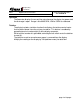
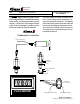
Increase/Decrease in pipe size The transmitter can be placed after an increase in pipe
diameter, never after a decrease.
Class1
flexible hose can greatly assist in reducing the number of elbows and amount of
turbulence between the pump and discharge pipe.
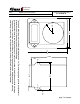
Wiring
The Flowminder system comes with a wiring harness that connects the transmitter
to the display.
The OEM must supply power and ground to the digital display. Consideration
should be given to the conditions under which the display will have power.
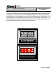
The display is internally protected against short circuits, overvoltage and reverse
polarity, but standard installation procedures should provide for circuit protection.
Maximum current used by the flowmeter is 1.5 Amps.
A momentary grounding switch can be added when the totalizer function is desired.
This is connected to the display through the 8 pin mini-connector at pin 8.