
Owner's manual
page 5 of 9 pages
Engineering
Standards
Name
Identifier
Engineering Standard Number
C1-102046-A
Digital Flowmeter Information
Installation and Calibration Information
5. Calibration
Flowmeter Calibration is performed with the discharge stabilized at the desired calibra-
tion flow. (Smoothbore nozzle and Pitot gauge)
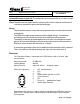
The calibration mode is entered by the use of a “password”.
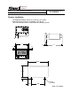
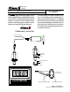
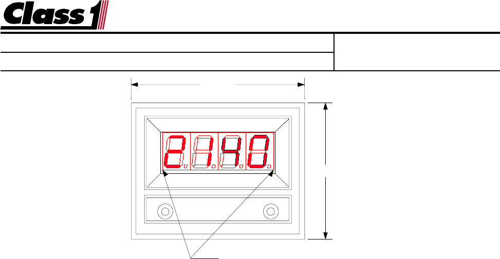
There are two magnetic switches located at the lower corners of the display.
These switches are activated with the use of a magnet, switch activation is visually
confirmed by the lighting of the closest decimal point on the display.
Enter the switch sequence below to enter calibration mode.
Left Switch Left Switch Left Switch Right Switch Right Switch Right switch
LEFT LEFT LEFT RIGHT RIGHT RIGHT
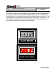
If the password is correctly entered, “
Cal Cal
Cal Cal
Cal
” will be displayed for 1/2 second followed
by “
0 0
0 0
0
”.
Hold the magnet on the right switch until the display reads the Gallons per Minute
(GPM), Liters per Minute (LPM) or Imperial Gallons per Minute (IGPM) that you are
flowing. The speed with which the display increments/decrements the calibration flow
display increases as the switch is held. If you pass the flow value, release the switch
and reactivate. The display will “reverse direction” each time the switch is activated
and the speed will start out at the slowest rate. Maintain the calibration flow for a mini-
mum of 10 seconds to assure an accurate and stable calibration before activating the
left switch. When the flow is stable and the calibration flow rate is entered into the
display, activate the left switch to complete calibration.
The display will read “
donE donE
donE donE
donE
”
followed by the current flow rate in GPM.
Calibration is now complete.
6. Operation
The Flowminder will display the current flowrate whenever the display is enabled
and the discharge is open. Range is 0 to 9990 GPM, LPM or IGPM.
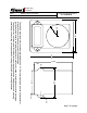
Location of magnetic switches
2.462"
3.125"