
Instruction manual


24 Distributed Audio Panel Manual — P/N 52265:B1 6/8/2010
Product Description Getting Started
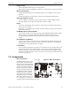
1.7.1 ACC-25/50 With ACC-25/50DA(s), System Requiring More
Than 50 Watts of Audio Power
• Connect the Audio Riser and Master Command Bus (for All-Call) cabling between the ACC-
25/50 and ACC-25/50DA panels. Refer to Section 5, 'Application Examples' on page 59.
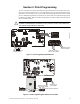
• Install backboxes and circuit boards as described in Section 3, 'Installation' on page 33.
• Configure the ACC-25/50 for Single Zone operation using DIP switch S3 switches 1, 2 and 3
on the ACC-MCB motherboard. Refer to Section 2, ‘Field Programming’ in the ACC-25/50
Series Manual. The ACC-25/50DA DIP switches can be left at the default settings.
• If the optional message generator is installed, record any new voice messages as described in
Section 4, 'Operating Instructions' on page 52.
1.7.2 ACC-25/50ZS/T With ACC-25/50DAZS, System Requiring
More Than 50 Watts of Audio Power
• Connect the Audio Riser and EIA-485 cabling between the ACC-25/50ZS/T and
ACC-25/50DAZS panels. Refer to Section 5, 'Application Examples' on page 59.
• Install backboxes and circuit boards as described in Section 3, 'Installation' on page 33.
• Configure the ACC-ZPMK on the ACC-25/50ZS with the number of ACC-25/50DAZS panels
connected on the Zone System serial link.
• Configure the address wheel located on the ACC-ZPM in the ACC-25/50DAZS panel.
• If the optional message generator is installed, record any new voice messages as described in
Section 4, “Operating Instructions”, on page 52.