
Instruction manual


132 JUPITER CM-4400 Control Module Installation and Operating Manual
Section 5 — The Configurator Application
Not all tables will apply to every system. For example, some are for
machine control, others are for backward compatibility with Philips/BTS
Party Line equipment, etc. Please refer to the description of each table for
more information.
Using the Numeric Sets for Quick Switcher Checkout
The factory-supplied numeric configuration sets can be used to set up and
operate the routing switcher in the minimum possible time. The
“NUMERIC” set may be used with a switcher with up to 256 inputs, 256
outputs, and four levels; the “NUM-64” set provides for 64 inputs and out-
puts; and the “NUM-128” set provides for 128 inputs/outputs.
The numeric sets are complete and ready to download, except for entry of
at least one CM-4400 Contr
ol Chassis address, entry of the actual switcher
Physical Levels and Driver types, and one switcher control panel address.
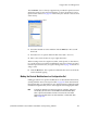
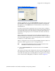
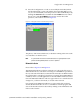
1. Use the “File > Open” menu to select one of the Numeric sets
2. Make a copy of the Numeric set.
3. Select the Network Description table (Jupiter > Network Description
table).
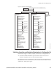
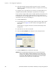
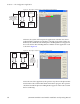
4. Change the address of the CM-4400 to match those in your system. The
actual switcher Physical Levels and Driver types are entered on the
Switcher Description table. The control panel address must be entered
on the MPK Devices Description table.
The set can then be compiled and activated
as described in Validating, Com-
piling, and Activating (Downloading) a Configuration
Set on page 133.
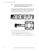
Inputs and outputs are selected numerically
, using the TEST key on a CP
3000 control panel to enter a leading zero for selections zero through 99.
The VTR key is used to enter a “1,” and so on.