
Instruction manual


174 JUPITER CM-4400 Control Module Installation and Operating Manual
Section 5 — The Configurator Application
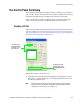
Entering the Level Information
Follow these steps to enter the information in the CP Level Set table:
1. Enter a name or an ID in the Mnemonic column. The information in the
Mnemonic column of this table is the source for the ID of each level that
will appear on control panels during input selection.
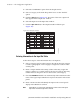
2. Select the preferred option from the Level drop-down list. The Level
column determines the order in which the switcher levels will appear
in the control panel status display. Video is normally listed first. In the
example shown in Figure 123 on page 173, the order from left to right
will be video, left audio, right audio, and time code. The first level
entered will also be the level statused where display space is limited.
The Break and Switch check boxes are not supported by AccuSwitch.
3. Save the changes by selecting Save from the File menu (File > Save).
4. Click the OK button to save the table.
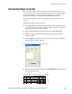
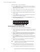
Level Numbering and External Control Computers Using the ASCII Protocol
The ASCII protocol switching instructions include specification of output,
input, and level; with level indicated by a number from 1 to 7. These level
numbers correspond to the order in which levels are listed on the CP Level
Set table. In the example table shown in Figure 123 on page 173, the ASCII
level numbers would apply to the switcher levels as follows:
Do not confuse these ASCII level numbers with the logical and physical
level numb
ers of the switcher, which may be different. (The level names on
this table are translated to logical and physical level numbers on the
Switcher Description table.) For more information see ASCII protocol.
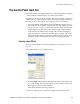
Table 9. Level Numbering Using the ASCII Protocol
Level number used with ASCII protocol Example level shown on CP Level Set table
1VIDEO
2 LEFT
3 RIGHT
4T/C