
Instruction manual


196 JUPITER CM-4400 Control Module Installation and Operating Manual
Section 5 — The Configurator Application
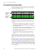
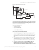
Following hardware installation, path finding requires entries to the Path
Finding Data table and selection of Group Names numbers on the Switcher
Input tables (Figure 142 on page 194).
If the tie lines are wired non-sequentially, please refer also to The Non-
Sequential Path Finding Table on page 200.
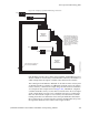
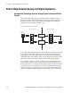
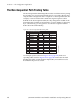
Path Finding For Three or More Switchers
It is possible to connect three switchers for path finding purposes. The rec-
ommended maximum is five switchers. This is illustrated in Figure144.
Notice that no tie lines directly connect switcher “A” and switcher “C.”
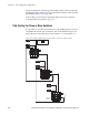
Figure 144. Example of path finding connections between video levels of three switchers
Distribution
switcher “A”
Distribution
switcher “B”
Distribution
switcher “C”
Tie lines
Video
071876600_pathfinding3switchers.