
Instruction manual


JUPITER CM-4400 Control Module Installation and Operating Manual 199
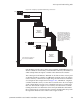
Path Finding Between Analog and Digital Equipment
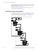
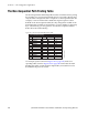
Figure 146. Example of Automatic Conversion System
The system in the example would require four tie lines, with a dedicated A
to D converter connected to the first pair and a dedicated D to A converter
connected to the second pair. Each pair is locked together, meaning that
selection of one result in selection of both.
The corresponding tables are:
•Switcher Description
•
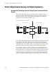
Sequential Path Finding
• Switcher Input-MAINROUT
• Switcher Output-MAINROUT
There are three rules governing this technique:
1. The path finding groups, in the Sequential Path Finding table, that are
to be locked together MUST have identical digital Switcher Names,
digital Level Names, and digital Physical Input/Output entries. These
groups must be on consecutive rows of the Sequential Path Finding
table.
2. In the Switcher Description table, the “MAINROUT LEFT” level and
“MAINROUT RIGHT” level must be controlled by the same CM.
However, the “MAINROUT AES” level may be controlled by another
CM.
3. Any levels “sourced” by, in this case, the MAINROUT LEFT and
RIGHT levels may not break away. This must be established by
removing the check in the “Breakaway” check box in the CP Level Set.
01
16
17
“MAINROUT
LEFT”
A TO D
CONVERTER
D TO A
CONVERTER
18 19
26
27
“MAINROUT
AES”
“VTR1”
(ANALOG)
6
7
“MAINROUT
RIGHT”
45
“VTR2”
(DIGITAL)
TIE LINE GROUP 1
TIE LINE GROUP 3
TIE LINE GROUP 4
TIE LINE GROUP 2
071876600_autoconvsystem