
Instruction manual


62 JUPITER CM-4400 Control Module Installation and Operating Manual
Section 2 — Hardware Installation
Logical Level Mapping
The Jupiter Physical Switching menu refers to a “logical level” that is actu-
ally the logical level number; t
his number is the row number that the level
is identified on the Switcher Level Descriptions table. The logical level
name also appears on this table
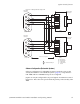
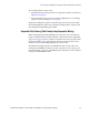
In redundant systems, the same physical level number is
used on more
than one logical level. For example, a switcher could have video on level 1,
left audio on level 2, and right audio also on level 2. In Figure26, a 60 x 60
audio level is being used as two 60 x 30
switchers with half the outputs
assigned to the left channel and the other half to the right channel.
This technique can help reduce the overall
switcher size, but requires
special entries to the Switcher Description table and the Switcher Outputs
table.
Figure 26. Example of Logical Level Mapping
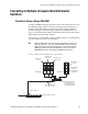
Data Matrix Switching
The Jupiter system can be used to control RS-232, RS-422, and RS-423 data
switchers. In a typical application, a data matrix switcher can be used to
route RS-422 machine control signals.
Newer model router systems are equippe
d with the DM 400B Data Matrix
boards; these boards have software-configurable rear-panel pinout func-
tions and do not require crossover or Y-line cables.
CC−2010 Matrix cables
CB 3000 Control Buffer
See diagram on
page 2−3 for
cabling details.
Physical level 1
60 x 60 video
Physical level 2
60 x 60 audio
used as
60 x 30 Left
and
60 x 30 Right
Crosspoint Bus port
CM-4400 System Controller
House SMPTE
time code required
for deterministic
switching
House sync
required for
vertical inter-
val switching.
LAN