
Instruction manual


74 JUPITER CM-4400 Control Module Installation and Operating Manual
Section 2 — Hardware Installation
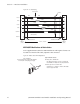
Installing Control Panels
See the manual that came with the preferred Control panel for Installation
instructions, including hardware connections and entries to Jupiter config-
uration tables.
Note A maximum of sixteen devices may be assigned to an addressable controller
port. For more information about calculating load factor, see the recom-
mended maximum number of devices see CM-4400 Serial Bus Loading on
page 315
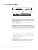
Sync Reference Cables
A video reference (sync) signal should be connected to each CM-4400. This
signal may be color black or composite sync with an amplitude between 1
V P-P and 4 V P-P.
The CM-4400 System Controller must have a sync reference in order for a
G
rass Valley Crosspoint Bus router to switch during the house vertical
interval. Crosspoint Bus routers are listed in Supported Routers on page 285.
Time Code Connections
Time code must be connected to the CM-4400 for deterministic switching.
A time code connection to the CM-4400 also provides an accurate date and
time stamp for JNS Logger messages.
The CM-4400 clock and the file server cl
ock can be synchronized by refer-
encing them to the same time source, such as a time code input (preferred)
or a Network
Time Protocol server.
For more information see The Time Standard Table on pa
ge 204.
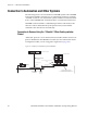
Connecting to a Master Control
AccuSwitch interfaces with Master Control devices for router switch com-
mands only.
See the manual that came with the pr
eferred Master Control device for
Installation instructions, including hardware connections and entries to
Jupiter configuration tables.