
Instruction manual


JUPITER CM-4400 Control Module Installation and Operating Manual 77
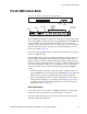
The CB 3000 Control Buffer
The CB 3000 Control Buffer
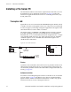
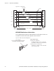
Figure 36. The CB 3000 Control Buffer - Front and Rear Panel
The CB 3000 Control Buffer is required for buffering crosspoint data when
the Crosspoint Bus is sent to more than one equipment rack. A CB 3000 may
also be needed if the system includes more than one router type (For
example, a Trinix and an Apex) and one of the routers is at or near the bus
limit. For more information, contact Grass Valley Tech Support (see Con-
tacting Grass Valley on pa
ge 4).
Each of the eight CB 3000 outputs can drive up to 50 (TVS/TAS) or up to 96
(V
enus) crosspoint boards.
Each CB 3000 output contains two identical channels, with channel A nor-
mally used; this condition is indicated
by the eight green LEDs in the
display window. If a fault is detected in channel A, that output will auto-
matically switch to channel B; in this cas
e the green LEDs would be off and
one or more red LEDs would be on. If a changeover occurs, first check to
see if the unit will return to normal operation by pressing the
Select A
button:
• If the unit returns to channel A operation, but a red LED remains on,
pr
ess the
Clear button on the front of the CB 3000 (Figure36). If the red
LEDs turn off, it can be assumed that the unit is fully operational.
• If the unit immediately returns to channel B operation, contact Grass
Valley Technical Support (see Contacting Grass Valley on page 4). For a
description of the front panel window LEDs (see CB 3000 Crosspoint
Buffer and Interface on page 241.)
Router Requirements
Apex audio routers do not require a CB 3000-regardless of system expan-
sion-because the crosspoint bus is connected only to one chassis.
For Trinix requirements, please refer to
the Planning section of the Trinix
Planning and Installation Manual.
SELECT
A
SELECT
B
CLEAR
A
POWER
B
POWER
REM/ALM
OUTPUT
(CONTROL)
BUSES
CROSSPOINT
BUS LOOP