
Owners Manual


8
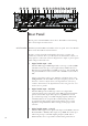
Front Panel
e front panel of the Delta PRE is shown above. e numbers in the drawing
refer to the descriptions that follow.
1 Standby/On Button and Status Indicator LED
Pressing the Standby button puts the Delta PRE into standby mode – a
low-power state which leaves the preamp/processor and outputs inactive
but still allows the unit to respond to system commands via any of the
supported control protocols (LAN, CAN-Bus or RS-232)*.
If the unit is already in Standby mode, pressing the Standby button fully
powers up the unit.
• LED On (Red) – the Delta PRE is in Standby mode.
• LED turns green, then white – the Delta PRE is in the process of
power-up initialization.
• LED On (white), indicates the unit is in the operate mode.
• LED Flashing (blue), indicates the unit is updating rmware.
• LED Flashing (red), indicates a problem during startup.
•
LED O – the Delta PRE is not getting AC power.
*See section on Advanced Settings: Wake-on-Network must be enabled
to allow controllers to wake the unit from Standby.
e Standby button also serves as a data save mechanism. Each time the
Standby button is pressed, the Delta PRE will saves all custom settings
made during its last operation. If power is lost before pressing standby, all
pending changes will be lost.
2 Touchscreen
e front panel touchscreen is used for day-to-day operation of the Delta
PRE. It is also used for setup and to display useful information as required.
Touch the screen anywhere on this Home page to access sources.
3 Menu On/Off Button
Press once to call up the main page of the menu system. Press the Menu
button again to revert to the Home page.
Delta PRE
Delta PRE
1 6 2 3 4 5 7