SOD CUTTER OPERATOR’S/PARTS MANUAL SC-12 SC-16 SC-18 SC-20 SC-24 Schiller-Pfeiffer, Inc.
TABLE OF CONTENTS INTRODUCTION . . . . . . . . . . . . . . . . . . . . . . . . . . . . . . . . . . 1 Thank You . . . . . . . . . . . . . . . . . . . . . . . . . . . . . . . . . . . . 1 Read This Manual . . . . . . . . . . . . . . . . . . . . . . . . . . . . . . 1 Warranty . . . . . . . . . . . . . . . . . . . . . . . . . . . . . . . . . . . . . . 1 Measurements. . . . . . . . . . . . . . . . . . . . . . . . . . . . . . . . . . 1 Serial Numbers . . . . . . . . . . . . . . . . . . . . . . . . . . . . . . . .
INTRODUCTION THANK YOU Thank you for purchasing the Classen Model SC-20, SC-18, or SC-12 sod cutter. PRE-DELIVERY CHECK LIST Check the following before you deliver the sod cutter to the customer. 1. Guards and shields fastened in place. 2. Decals fastened and legible. 3. Tire pressure. 4. Gas lever on engine turned on. 5. All eight lubrication points greased. This manual should be considered a permanent part of your sod cutter and should remain with it if you sell it. 6. 2:1 gearbox oil level.
ENGINE STARTING PROCEDURES SAFETY HANDLE FUEL SAFELY - AVOID FIRES Handle gasoline with care; it is highly flammable. Use an approved gasoline container. DO NOT remove gas cap if engine is running. NOTICE: There are two locations on this engine that require oil, both the crankcase and the transmission (gearbox). Running the engine or gearbox with a low oil level can cause engine damage. Refer to the engine manual for complete engine information and recommendations.
OPERATING THE SOD CUTTER PREPARATION 1. Police lawn area for obstacles and debris (i.e. sprinklers, hoses, toys, etc.). Remove all items. 2. Make sure underground sprinkler heads and other hidden obstacles are marked to prevent damage. 3. Mark other areas where sod cutting will be a problem or too risky (i.e. mud, tree roots, steep hills). OPERATING 1. Start the engine. CAUTION: To avoid injury, do not place your feet or other body parts under the blade while starting the engine. 2.
TROUBLESHOOTING CHART PROBLEM CAUSE REMEDY Blade will not stay in ground a. Bottom of blade is rounded off a. Blade should be sharpened or replaced Belts jump off a. Wrong type of belt b. Pulley misalignment a. Use only the special factory belt b.
SOD CUTTER PARTS MANUAL SC-12/5.5 SC-12/8.0 SC-16/5.5 SC-18/5.5 SC-18/8.0 SC-20/5.5 SC-20/8.0 SC-24/8.0 – – – – – – – – S.N. S.N. S.N. S.N. S.N. S.N. S.N. S.N.
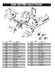
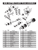
SOD CUTTER MAIN FRAME 4 7 44 6 1 9 10 5 6 3 20 10 7 8 10 13 14 8 2 8 7 12 25 26 25 20 7 32 31 25 20 24 30 22 11 23 25 31 28 23 22 25 33 42 23 22 23 17 27 21 8 43 22 15 22 23 7 9 25 23 10 35 24 34 25 6 7 16 46 29 26 17 6 7 45 SC-12 SC-16 48 47 7 SC-24 6 19 18 SC-20 48 6 KEY 1 2 3 4 5 6 7 8 9 10 11 12 13 14 15 16 17 18 19 20 21 22 23 24 25 26 27 28 6 PART NO.
SOD CUTTER POWER TRAIN ASSEMBLY 45 11 10 11 43 10 14 39 8 27 1 49 48 7 8 13 14 14 6 47 40 14 10 48 15 16 16 13 14 2 25 33 17 41 42 3 34 12 18 44 17 9 19 25 5 41 42 27 20 29 24 9 4 46 26 18 29 21 22 23 17 19 23 30 28 31 35 22 32 38 37 21 22 23 28 36 KEY 1 1 2 3 3 4 5 6 7 8 9 10 11 12 13 14 15 16 17 18 19 20 21 22 23 24 PART NO.
SOD CUTTER HANDLE ASSEMBLY 2 4 40 3 5 28 2 29 9 7 1 8 13 10 11 6 12 15 21 49 6 30 22 24 23 23 6 16 17 4 28 4 29 18 6 20 6 KEY 1 2 3 4 5 6 7 8 9 10 11 12 13 14 14 14 14 14 15 16 17 18 19 20 21 22 23 8 PART NO.
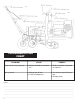
38 10 D 34 SEE DIAGRAM A 35 33 50 37 33 32 9 36 SEE DIAGRAM B 31 39 41 10 33 32 40 SEE MAIN FRAME PAGE FOR BLADE ADAPTOR PART NUMBERS 42 14 32 22 23 4 43 40 40 24 DIAGRAM A 48 RAM A 43 44 45 26 43 47 DIAGRAM B 44 NOTE: When installing seals, make sure spring side of seal is away from bearing.
Schiller-Pfeiffer, Inc. 1028 Street Road • Southampton, PA 18966 Telephone: 1-800-366-6268 ONE YEAR LIMITED WARRANTY Effective January 1, 1994 For the period of one year from the date of purchase, CLASSEN MFG., INC. will repair or replace for the original purchaser (90 days if used for rental purposes) free of charge, any part or parts found upon the examination of our factory authorized service station, or by the factory in Norfolk, Nebraska, to be defective in material or workmanship.
CORTADOR DE TEPE MANUAL DEL OPERADOR/PIEZAS SC-12 SC-16 SC-18 SC-20 SC-24 Schiller-Pfeiffer, Inc.
ÍNDICE INTRODUCCIÓN. . . . . . . . . . . . . . . . . . . . . . . . . . . . . . . . . . 1 Gracias . . . . . . . . . . . . . . . . . . . . . . . . . . . . . . . . . . . . . . . 1 Lea este manual . . . . . . . . . . . . . . . . . . . . . . . . . . . . . . . . 1 Garantía . . . . . . . . . . . . . . . . . . . . . . . . . . . . . . . . . . . . . . 1 Mediciones . . . . . . . . . . . . . . . . . . . . . . . . . . . . . . . . . . . . 1 Números de serie . . . . . . . . . . . . . . . . . . . . . . . . . . . . . . .
INTRODUCCIÓN GRACIAS Gracias por comprar el cortador de tepe Classen modelo SC20, SC-18 o SC-12. LISTA DE COMPROBACIÓN ANTERIOR A LA ENTREGA Compruebe lo siguiente antes de entregar el cortador de tepe al cliente. 1. Protectores y pantallas sujetos en posición. 2. Calcomanías sujetas y legibles. 3. Presión de los neumáticos 4. Palanca de gasolina del motor en la posición encendida. 5. Los ocho puntos de lubricación engrasados.
SEGURIDAD MANIPULE EL COMBUSTIBLE CON CUIDADO – EVITE LOS INCENDIOS Manipule la gasolina con cuidado, ya que es muy inflamable. Use un recipiente de gasolina aprobado. Llene el depósito de combustible al aire libre. NO llene el depósito completamente. NO fume mientras llene el depósito de combustible. NO quite la tapa de la gasolina con el motor en funcionamiento. LEA LOS LETREROS DE SEGURIDAD Lea detenidamente y siga las instrucciones de todas las calcomanías de precaución.
OPERACIÓN DEL CORTADOR DE TEPE PREPARACIÓN 1. Observe el área del césped para ver si hay obstáculos y objetos sueltos (por ejemplo, aspersores, mangueras, juguetes, etc). Quite todos los componentes. 2. Asegúrese de que las cabezas de los aspersores subterráneos y otros obstáculos ocultos estén marcados para impedir daños. 3. Marque otras áreas en que el corte de tepe pueda ser un problema o demasiado arriesgado (por ejemplo, barro, raíces de árboles, cuestas inclinadas). OPERACIÓN 1.
Tuerca del manillar de 1/2” Control de giro del acelerador Perno de ajuste de altura Barra de ajuste de altura Manillar de impulsión de las ruedas (lado izquierdo) Perno de ajuste de inclinación Manillar de la hoja de corte (lado derecho) CUADRO DE LOCALIZACIÓN Y RESOLUCIÓN DE PROBLEMAS PROBLEMA CAUSA SOLUCIÓN La hoja no permanece en el terreno a. La parte inferior de la hoja está redondeada a. La hoja debe afilarse o reemplazarse Las correas saltan y se salen a. Tipo de correa equivocado b.
CORTADOR DE TEPE MANUAL DE PIEZAS SC-12/5.5 SC-12/8.0 SC-16/5.5 SC-18/5.5 SC-18/8.0 SC-20/5.5 SC-20/8.0 SC-24/8.0 – – – – – – – – N/S N/S N/S N/S N/S N/S N/S N/S 000372 000136 000104 003956 000413 000141 000164 000147 y y y y y y y y sig. sig. sig. sig. sig. sig. sig. sig.
BASTIDOR PRINCIPAL EL CORTADOR DE TEPE 4 7 44 6 1 9 10 5 6 3 20 10 7 8 10 13 14 8 7 12 25 8 2 26 25 20 7 32 31 25 20 24 30 22 11 23 25 31 28 23 22 25 33 42 23 22 23 17 27 21 8 43 22 15 22 23 7 9 25 23 10 35 24 34 25 6 7 16 46 29 26 17 6 7 45 SC-12 SC-16 48 47 7 SC-24 6 19 18 SC-20 48 6 CLAVE 1 2 3 4 5 6 7 8 9 10 11 12 13 14 15 16 17 18 19 20 21 22 23 24 25 26 27 28 6 N° DE PIEZA.
CONJUNTO DEL TREN DE FUERZA DEL CORTADOR DE TEPE 45 11 10 11 43 10 14 39 8 27 1 49 48 7 8 13 14 14 6 47 40 14 10 48 15 16 16 13 14 2 25 33 17 41 42 3 34 12 18 44 17 9 19 25 5 41 42 27 20 29 24 9 4 46 26 18 29 21 22 23 17 19 23 30 28 31 35 22 32 38 37 21 22 23 28 36 CLAVE 1 1 2 3 3 4 5 6 7 8 9 10 11 12 13 14 15 16 17 18 19 20 21 22 23 24 N° DE PIEZA.
CONJUNTO DE EMPUÑADURA DEL CORTADOR DE TEPE 2 4 40 3 5 28 2 29 9 1 8 7 13 10 11 6 12 15 21 49 6 30 22 23 24 23 6 16 17 4 28 4 29 18 6 20 6 CLAVE 1 2 3 4 5 6 7 8 9 10 11 12 13 14 14 14 14 14 15 16 17 18 19 20 21 22 23 8 N° DE PIEZA. C100018 C400006 C300068 C500043 C100019 C500041 C500118 C500136 C500137 C100007 C400008 C500019 C500139 C100029 C100416 C100016 C100110 C100329 C500154 C500042 C400074 C500025 C500026 C500134 C500146 C500133 C500101 CADA.
38 10 D 34 VEA EL DIAGRAMA B SEE DIAGRAM A 35 33 50 37 33 32 9 VEA ELSEE DIAGRAMA A B DIAGRAM 36 31 39 41 10 33 32 40 CONSULTE EN LA PÁGINA DEL BASTIDOR SEE MAIN FRAME PRINCIPAL LOS NÚMEROS DE PIEZA DEL PAGE FOR BLADE ADAPTADOR DE LA HOJA ADAPTOR PART NUMBERS 42 14 32 22 23 4 43 40 40 24 DIAGRAMA A DIAGRAM A 48 RAM A 43 44 45 26 43 47 DIAGRAMA BB DIAGRAM 44 NOTA: Al instalar sellos, asegúrese de sure que el NOTE: When installing seals, make spring of del sealsello is away fro
Schiller-Pfeiffer, Inc. 1028 Street Road • Southampton, PA 18966 Teléfono: + (877) 596 6337 UN AÑO DE GARANTÍA LIMITADA En vigor el 1 de enero de 1994 Durante el período de un año contado a partir de la fecha de compra, CLASSEB MFG., INC.