ENGLISH ® ALPHA BEAM 700 C61360 INSTRUCTION MANUAL INDEX Page Contents 2 Safety information 3 Unpacking and preparation 4 Installation and start-up 5 Control panel 7 Menu setting 14 Maintenance 21 Technical information 21 Cause and solution of problems 22 Channel functions Congratulations on choosing a Clay Paky product! We thank you for your custom.
SAFETY INFORMATION • Installation Make sure all parts for fixing the projector are in a good state of repair. Make sure the point of anchorage is stable before positioning the projector. The safety chain must be properly hooked onto the fitting and secured to the framework, so that, if the primary support system fails, the fitting falls as little as possible. If the safety chain gets used, it needs to be replaced with a genuine spare.
UNPACKING AND PREPARATION 1 Lamp 700W (fitted into projector) 099101 2 x 183102/802 Packing contents - Fig. 1 2 3 45° 45° 45° 45° 45° UNLOCKED 45° LOCKED LOCKED ° 90 ° 90 UNLOCKED ° 90 ° 90 PAN Mechanism Lock and Release (every 90°) - Fig. 2 TILT Mechanism Lock and Release (every 45°) - Fig.
INSTALLATION AND START-UP 4 Installing the projector - Fig. 4 The projector can be installed on the floor resting on special rubber feet, on a truss or on the ceiling or wall. WARNING: with the exception of when the projector is positioned on the floor, the safety cable must be fitted. (Cod. 105041/003 available on request). This must be securely fixed to the support structure of the projector and then connected to the fixing point at the centre of the base.
CONTROL PANEL 6 Mains L N Connecting to the mains supply - Fig. 6 7 DMX 512 5 PIN 5 4 3 1 2 SCREEN SIGNAL SIGNAL DMX 512 5 DMX 512 3 PIN SIGNAL SCREEN 1 2 3 SIGNAL Connecting to the control signal line (DMX) - Fig. 7 Use a cable conforming to specifications EIA RS-485: 2-pole twisted, shielded, 120Ohm characteristic impedance, 22-24 AWG, low capacity. Do not use microphone cable or other cable with characteristics differing from those specified.
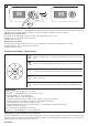
9 28 28 Reversal of the display - Fig. 9 To activate this function, press UP and DOWN keys simultaneously while the display is in the rest mode. This status will be memorised and maintained even for the next time it will be switched on. To return to the initial state, repeat the operation all over again. Setting the projector starting address On each projector, the starting address must be set for the control signal (addresses from 1 to 512). The address can also be set with the projector switched off.
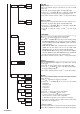
MENU SETTING MAIN MENU 1 2 Set Up Dmx Address 3 Option Lamp Dmx Pan / Tilt Channel Mode Information Invert Pan System Errors Fixture Hours Invert Tilt Lamp Hours Fixture ID Swap Pan-Tilt Ethernet Interface Lamp Strikes Encoder Pan-Tilt Option Color System Version Color Mixing Color mixing curve Information Board Diagnost.
NOTE: On grey the default options Set Up Dmx Address SET UP MENU DMX ADDRESS NOTE: without the DMX signal the Address (XXX) flashing Allows you to select the DMX ADDRESS. 1) Press - the current DMX Adress appear on the display. 2) Use the UP and DOWN , RIGHT keys to plan the DMX Address. 3) Press to confirm the selection or LEFT to keep current settings. Address xxx F B C E D F Channel Mode CHANNEL MODE Allows you to select a channel arrangement from the two available.
OPTIONS MENU LAMP DMX Used for enabling lamp remote control channel. 1) Press - the current settings appear on the display (On or Off). 2) Use the UP and DOWN keys to enable (On) or disable (Off) the lamp remote control channel. 3) Press to confirm the selection or LEFT to keep current settings. On Option Lamp Dmx Off F B C F Pan / Tilt Invert Pan D PAN / TILT Invert pan Used for reversing Pan movement. 1) Press - the current settings appear on the display (On or Off).
Shutter Shutter On Error SHUTTER Shutter on error Used for automatically closing the stop/strobe in the event of Pan/Tilt position error. 1) Press - the current settings appear on the display (On or Off). 2) Use the UP and DOWN keys to enable (On) or disable (Off) automatic stop/strobe closing in the event of Pan/Tilt position error. 3) Press to confirm the selection, or LEFT to keep current settings.
2) Select YES to confirm the selction or NO to keep current setting. OPTION DEFAULT Lamp DMX On Invert Pan Off Invert Tilt Off Off Swap Pan-Tilt Encoder Pan-Tilt On Color mixing CMY Color mixing curve Curve 1 Fixed Wheel Shortcut On Shutter on error Off Dimmer on Shutter Off Power Mode 4-700 Full fan speed Display On INFORMATION MENU Information SYSTEM ERRORS Shows a list of warnings and messages relevant to errors occurred since the fixtures switching-on.
F 2) Press to reset partial lamp strikes hours, a confirmation message (Are you sure ?) appears on the display. 3) Select YES to reset partial counter or NO to keep the current setting and return to the top menu level Revis. x.x.x x.x x.x x.x x.x Hw.rv. x.x System Version Board CPU brd com.dev 0: PT-3f 1: 8-Ch 2: 8-Ch Board Diagnost. Board 0:PT-3f 1:8-Ch 2:8-Ch Status Good Good Good Err% 0.00 0.00 0.
TEST MENU Test TEST Allows you to check the proper functioning of effects. 1) Press to return to the top menu level. 2) Use the UP and DOWN keys to select the required test. 3) Press to confirm the selection or LEFT to keep current settings.
MAINTENANCE 10 11 1 2 1 1/4 Turn 2 3 1/4 Turn 4 Locking and releasing Pan and Tilt movements - Refer to the instructions in the UNPACKING AND PREPARATION section. Opening the head covers - Fig. 10. Closing the head covers - Fig. 11.
12 13 A 1 Upper Side 1 2 2 Lower Side A 3 A Lamp change - Fig 13 Take the new lamp out of its package and insert in the fitting. WARNING: do not touch the lamp’s envelope with bare hands. Should this happen, clean the bulb with a cloth soaked in alcohol and dry it with a clean, dry cloth. IMPORTANT: Make sure the lamp is inserted with the external contact (A) facing the elliptical reflector’s slot. Opening and closing lamp compartment - Fig. 12 14 Upper Side Lower Side Lamp regulation - Fig.
15 Upper Side 2 1 085606/001 085802/001 085801/001 085910/001 Replacing fixed gobos (ø 31.5 mm – max 25 mm image – thickness max 1.1 mm) - Fig. 15 WARNING: Before using personalised gobos contact Clay Paky.
16 Upper Side 1 2 Bearing group replacement - Fig. 16 17 1 085526/001 085525/001 085527/001 085524/001 085528/001 085523/001 085506/001 2 Replacing rotating gobos (ø 25.7 mm - max 23 mm image – thickness max 1.1 mm) - Fig. 17 IMPORTANT: Use only glass gobos on the rotating gobos wheels. WARNING: Before using personalised gobos contact Clay Paky.
19 WARNING: The use of alcohol or any other detergent could da mage the lens Upper Side Cleaning the Fresnel lens Only use neutral soap and water to clean the Fresnel lens, then dry it carefully with a soft, non-abrasive cloth. Parts requiring frequent cleaning. Periodical cleaning - Fig. 19 To ensure optimal operation and performance for a long time it is essential to periodically clean the parts subject to dust and grease deposits.
20 Upper Side 1 2 Lower Side 3 thermostat 4 Extraction of the effect modules: Preliminary operations - Fig.
21 Upper Side Upper Side 2 1 Lower Side Upper Side 5 8 3 4 Extraction of the effect modules - Fig. 21 IMPORTANT: Grasp the modules using the support structure and not the details which could get damaged. Insertion of the effect modules: Repeat the operations indicated in Fig. 20 and 21 in reverse order.
TECHNICAL INFORMATION IP20 protection rating • Protected against the entry of solid bodies larger than 12mm (0.47”). • No protection against the entry of liquids. Power supplies available 100-120V 50/60Hz 200-240V 50/60Hz Input power • 1050VA a 230V 50Hz. Lamp Discharge lamp.
CHANNEL FUNCTION ALPHA BEAM 700 CHANNEL MODE CHANNEL STANDARD VECTOR 1 CYAN CYAN 2 MAGENTA MAGENTA 3 YELLOW YELLOW 4 COLOUR WHEEL COLOUR WHEEL 5 STOP / STROBE STOP / STROBE 6 DIMMER DIMMER 7 DIMMER FINE DIMMER FINE 8 IRIS IRIS 9 STATIC GOBO CHANGE STATIC GOBO CHANGE 10 ROTATING GOBO CHANGE ROTATING GOBO CHANGE 11 GOBO ROTATION GOBO ROTATION 12 PRISM INSERTION PRISM INSERTION 13 PRISM ROTATION PRISM ROTATION 14 FROST FROST 15 FOCUS FOCUS 16 PAN PAN 17 PA
NOTE: On conclusion of resetting in case of absence of DMX signal, Pan & Tilt move to the "Home" position (Pan 50% - Tilt 50%) all the others channels stay at 0%. • DIMMER - channel 6 • COLOUR MIXING - channel 1 - 2 - 3 Operation with option color mixing: RGB CHANNEL 1 CHANNEL 2 CHANNEL 3 CYAN MAGENTA YELLOW BIT % EFFECT 255 100 COLOUR EXCLUDED 0 0.0 COLOUR INSERTED BIT % 255 100 0 0.
• GOBO ROTATION - channel 11 MACRO • STATIC GOBO CHANGE - channel 9 BIT % EFFECT 255 100 GOBO 7 SHAKE, FAST SPEED 240 239 94.0 93.7 GOBO 7 SHAKE, SLOW SPEED GOBO 6 SHAKE, FAST SPEED 224 223 88.0 87.5 GOBO 6 SHAKE, SLOW SPEED GOBO 5 SHAKE, FAST SPEED 208 207 81.7 81.2 GOBO 5 SHAKE, SLOW SPEED GOBO 4 SHAKE, FAST SPEED 192 191 75.0 74.7 GOBO 4 SHAKE, SLOW SPEED GOBO 3 SHAKE, FAST SPEED 176 175 160 159 69.0 68.7 63.0 62.
• FROST - channel 14 BIT % 255 100 0 • PAN FINE - channel 17 Operation with option InvertPan Off (Tilt conventionally represented at 14% and option Invert Tilt G EFFECT GOff) FROST INSERTED BIT % 255 100 0 0.0 FROST EXCLUDED 0.0 • FOCUS - channel 15 G Operation with option InvertPan On (Tilt conventionally represented at 14% and option Invert Tilt BIT % 255 100 0 DISTANT NEAR 0.
• TILT FINE - channel 19 Operation with option Invert Tilt Off (Pan conventionally represented at 0% and option Invert Pan G BIT % 255 100 • LAMP CONTROL (only with option LAMP DMX On) - channel: 22 GOff) IMPORTANT: Alpha Beam 700 is not provided with hot restrike igniter BIT % 255 100 ON EFFECT LAMP ON (FULL POWER) Lamp ignition after 5 s in full power levels. Immediate transition from half to full power. SEL TX DMX S E ON ON 180 179 70.5 70.
TIMING CHANNELS Timing Channel Channel function 23 Pan - Tilt time Pan - Tilt - (Pan fine - Tilt fine) 24 Colour time CMY - Colour wheel 25 Beam time Dimmer - Frost - Iris - Prism insertion 26 Gobo time Static Gobo - Rotating Gobo Change TIME TABLE BIT 0 1 2 3 4 5 6 7 8 9 10 11 12 13 14 15 16 17 18 19 20 21 22 23 24 25 26 27 28 29 30 31 32 33 34 35 36 37 38 39 40 41 42 Seconds Full 0.2 0.4 0.6 0.8 1 1.2 1.4 1.6 1.8 2 2.2 2.4 2.6 2.8 3 3.2 3.4 3.6 3.8 4 4.2 4.4 4.6 4.8 5 5.2 5.4 5.6 5.8 6 6.
www.gfstudio.com Cod. 099101-EN Rev. 2 02/11 CLAY PAKY S.p.A. - Via Pastrengo, 3/b - 24068 Seriate (BG) Italy - Tel. +39-035-654311 - Fax +39-035-301876 - www.claypaky.