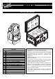
ENGLISH GLOW UP & FLIGHT CASE C TW W C71050 C71055 C71060 F21230 INSTRUCTIONS MANUAL Page 2 3 12 12 13 14 16 16 17 18 23 24 24 25 27 28 28 29 CONTENTS Contents Safety information GLOW UP EN-IT-FR-DE-ES Safety information FLIGHT CASE EN-IT-FR-DE-ES Unpacking and preparation Removal of the protective film Installation and start-up Control panel Shortcut keys menu Button function Preset colors for Stand Alone “GLOWUP C” Main menu Operating Mode RDM Controls implemented for GLOWUP series Manual zoom - A
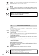
EN LED SAFETY INFORMATION GLOW UP • Installation Make sure all parts for fixing the projector are in a good state of repair. Make sure the point of anchorage is stable before positioning the projector. The safety chain must be properly hooked onto the fitting and secured to the framework, so that, if the primary support system fails, the fitting falls as little as possible. If the safety chain gets used, it needs to be replaced with a genuine spare.
LiFePO4 • Battery This product contains a lithium iron tetraphosphate rechargeable battery. To protect the environment, please discard the battery at the end of its life cycle according to current law. Disposing This product is supplied in compliance with European Directive 2012/19/EU - Waste Electrical and Electronic Equipment (WEEE). To preserve the environment please dispose/recycle this product at the end of its life according to the local regulation.
IT LED INFORMAZIONI DI SICUREZZA GLOW UP • Installazione Assicurarsi che tutte le parti per il fissaggio del proiettore siano in buona condizione. Assicurarsi della stabilità del punto di ancoraggio prima di posizionare il proiettore. La fune di sicurezza, debitamente agganciata all’apparecchio e fissata alla struttura di sostegno, deve essere installata in modo che, in caso di cedimento del sistema di supporto primario, si abbia la minor caduta possibile dell’apparecchio.
LiFePO4 • Batteria Questo prodotto contiene una batteria ricaricabile Litio Ferro Tetrafosfato. A tutela dell'ambiente si prega di smaltire la batteria a fine vita in conformità alla normativa vigente. Smaltimento Questo dispositivo è conforme alla Direttiva Europea 2012/19/UE - Rifiuti di apparecchiature elettriche ed elettroniche (RAEE). Nel rispetto dell'ambiente, smaltire/riciclare il prodotto al termine del suo ciclo di vita secondo le disposizioni di legge locali.
FR CONSIGNES DE SÉCURITÉ GLOW UP • Installation S’assurer que toutes les pièces pour la fixation du projecteur sont en bon état. S’assurer de la stabilité du point d’ancrage avant de positionner le projecteur. Le câble de sécurité, à fixer correctement à l’appareil et à la structure de support, doit être installé de façon à ce que, en cas de rupture du système de support principal, la chute de l’appareil soit la plus limitée possible.
LiFePO4 • Batterie Ce produit contient une batterie rechargeable au tétraphosphate de fer au lithium. Une fois la batterie parvenue à la fin de sa durée de vie, procéder à son élimination conformément à la norme en vigueur de manière à éviter toute pollution. Élimination Ce dispositif est conforme à la Directive Européenne 2012/19/UE – Déchets d’équipements électriques et électroniques (DEEE).
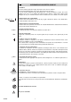
DE LED INFORMATIONEN ZUR SICHERHEIT GLOW UP • Installation Sicherstellen, dass alle Teile für die Befestigung des Projektors in einwandfreiem Zustand sind. Vor der Installation des Projektors die Stabilität der Verankerungsstelle überprüfen. Das korrekt am Gerät eingehakte und an der Haltestruktur befestigte Sicherheitsseil muss so installiert werden, dass bei einem Nachgeben der Haupthalterung die Fallhöhe des Gerätes so gering wie möglich ist.
LiFePO4 • Batterie Dieses Produkt enthält eine wiederaufladbare Lithium-Eisenphosphat-Batterie. Zum Schutz der Umwelt bitten wir Sie, diese Batterie, nachdem sie verbraucht ist, gemäß den geltenden Vorschriften zu entsorgen. Entsorgung Diese Vorrichtung entspricht der Europäischen Richtlinie 2012/19/UE - Abfall von elektrischen und elektronischen Gerätschaften (RAEE). Das Produkt am Ende seines Lebenszyklus unter Berücksichtigung der Umwelt nach den lokalen Gesetzesvorschriften entsorgen/recyceln.
ES LED INFORMACIONES DE SEGURIDAD GLOW UP • Instalación Asegúrese de que todos los elementos de fijación del proyector estén en buenas condiciones. Controle la estabilidad del punto de anclaje antes de instalar el proyector. La cuerda de seguridad, correctamente enganchada al aparato y fijada a la estructura de soporte, debe colocarse de modo que, si el soporte principal cede, el aparato sufra la menor caída posible. En caso de desgaste de la cuerda de seguridad, sustitúyala por el recambio original.
LiFePO4 • Batería Este producto contiene una batería recargable plomo-ácido o de Litio Tetrafosfato Hierro. Para proteger el ambiente se ruega eliminar la batería conforme a la normativa vigente. Eliminación Este dispositivo es conforme a la Directiva Europea 2012/19/UE - Residuos de equipos eléctricos y electrónicos (RAEE). Con el fin de respetar el ambiente, eliminar/reciclar el producto al final de su ciclo de vida según las disposiciones de ley locales.
UNPACKING AND PREPARATION 1 C71050 C TW C71055 C71060 W GLOW UP ® ITALIANO & FLIGHT MANUALE EL PR F21230 CASE ZIONI DI ISTRU Y AR IMIN INDICE o Contenut oni di sicurezza Informazi izione e predispos Disimballo in funzione ne e messa Installazio Pag.
INSTALLATION AND START-UP 3 Projector installation - Fig. 3 The projector can be installed on the floor resting on specific rubber feet, on a truss, on the ceiling or wall. WARNING: the safety chain must be installed except when the projector rests on the floor. (Code 105015/801 available upon request). This must be secured to the projector support structure and then hooked to the fastening point at the centre of the base. 4 4 1 1 3 3 2 2 Connecting and disconnecting the power cord - Fig.
CONTROL PANEL Power Supply 5 L N Connections to the power mains - Fig. 5 6 DMX 512 5 PIN DMX 512 5 4 3 1 2 SCREEN SIGNAL SIGNAL Connections to the control signal line (DMX) - Fig. 6 Use a cable conforming to specifications EIA RS-485: 2-pole twisted, shielded, 120Ω characteristic impedance, 22-24 AWG, low capacity. Do not use microphone cable or other cable with characteristics differing from those specified. End connections must be made using XLR type 3-pin male/female connectors.
When GlowUp is in idle status the information page will appear on the display: DMX Address Operating mode (see page 23) ADDR 001 DMX C Yy Link status (Wireless or Wired) Display symbology - (Link Status) Transmission to DMX cable BAT 40% W Time or percent remaining of the battery charge Warning Radio W42 (radio board not found) W43 (radio board not interact) If errors W42/W43 appear on the display, do an RDM Discovery (see page 16) to see if the error disappears.
SHORTCUT KEYS MENU By pressing the ENTER A key and UP B, the DMX address setting function can be quickly accessed.
PRESET COLORS FOR STAND ALONE “GLOWUP C” Colour 01 02 03 04 05 06 07 08 09 10 11 12 13 14 15 16 17 18 19 20 21 22 23 24 25 26 27 28 29 30 31 32 33 34 35 36 37 38 39 40 41 42 43 44 45 46 47 48 49 50 51 52 RGBW RED GREEN BLUE YELLOW CYAN MAGENTA WHITE ORANGE PINK VIOLET AQUA SKY BLUE FULL WHITE COOL WHITE WARM WHITE WHITE 3200 WHITE 2500 YELLOW 2 STRAW ORANGE LIGHT ROSE DARK PINK MAGENTA BLUE 2 MED BLUE GREEN DARK BLUE BRIGHT PINK MEDIUM BLUE GOLDEN AMBER DEEP GOLDEN AMBER PALE LAVENDER APRICOT DARK LAVENDER
1 Program Edit scene 2 MENU SET DMX Address 3 Advanced Setup Radio Mode Edit Sequence Lock Option DMX recorder Display Contrast Battery Display Fixture ID Set Model Color Tunable White White FW Uploader Appl. Upload Boot.
Program PROGRAM MENU EDIT SCENE To create/overwrite/modify a SCENE customised by the user: – SCENE 1 appears on the display. 1) Press ENTER 2) Use the UP and DOWN keys to select from the ten available SCENES. 3) Press ENTER to open a SCENE. 4) A value can be associated with each GlowUp channel inside each and DOWN keys. SCENE using the UP 5) When finished with settings, press SELECT . A confirmation message appears: SAVE SCENE X ?.
Advanced Setup MODE Assigns the desired command to the GlowUP Radio module 1) Press ENTER – current settings appear on the display.
Advanced Setup CONTRAST Lets the user modify display contrast. 1) Press ENTER – current settings appear on the display. 2) Use the UP and DOWN keys to modify the value from 0 to 10 according to the desired contrast. 3) Press SELECT to return to the previous Menu. Contrast A B S C A B C BATTERY DISPLAY Allows you to select how to display the battery charge in idle status. 1) Press ENTER – current settings appear on the display.
Advanced Informations TOTAL LED HOURS Displays total LED working hours, from construction to today. 1) Press ENTER – total LED working hours appear on the display. 2) Press SELECT to return to the previous Menu. Total LED hours A S SYSTEM VERSION Displays the version of the firmware loaded on the CPU board. 1) Press ENTER – two options appear on the display: Application release Boot release (Backup Software) 2) Use the UP and DOWN keys to select which of the two firmware version items to be displayed.
Advanced "Repeater"-> "Function"->"Repeat & Play" "Repeater"-> "Direction"->"Wirel. to Cable" ‘’DMX address’’ = 1 "Display"-> Off “Contrast” = 5 “MOD”-> "Stand Alone/DMX" "Slave Priority"-> "Cable" Reset CPU RESET Used to reset the CPU. Settings will not be reset. 1) Press ENTER – a confirmation message appears on the display (OK?) 2) Press ENTER to RESET or SELECT to return to the previous Menu. CPU Reset A A S TEST Used to test the correct operations of effects. 1) Press ENTER .
RDM CONTROLS IMPLEMENTED FOR GLOWUP SERIES Control DEVICE_INFO IDENTIFY_DEVICE DMX_START_ADDRESS PID 0x0060 0x1000 0x00F0 GET X 0x00C0 X PARAMETER_DESCRIPTION 0x0051 X DMX_PERSONALITY_DESCRIPTION 0x00E1 X DEVICE_LABEL 0x0082 X DMX_PERSONALITY MANUFACTURER_LABEL 0x0050 0x00E0 0x0081 SENSOR_DEFINITION 0x0200 RECORD_SENSORS 0x0202 SENSOR_VALUE DEVICE_MODEL_DESCRIPTION 0x0201 0x0080 X X SOFTWARE_VERSION_LABEL SUPPORTED_PARAMETERS SET X Description controller side Gathers inf
MAINTENANCE 9 4 3 1 2 Charging glow up - Fig. 9 From 1 to 6 Glow Ups can be simultaneously charged by appropriately connecting and powering the flight-case. 10 1 Fuse 6,3x32mm 3AT 250Vac (030471) 2 Fuse 6,3x32mm 10AT 250Vac (030470) Replacing flight case fuses - Fig. 10 Each flight-case has 2 fuses associated with the main power cord connection and one fuse for each Glow UP charge station.
11 3 2 1 5 6 4 Battery removal - Fig. 11 This product contains lithium iron tetraphosphate rechargeable battery. To protect the environment, please discard the battery at the end of its working life according to current law. LiFePO4 GLOW UP Notes on how to achieve correct battery operations 1) Do not tamper with the control electronic circuit, do not tamper with the battery, do not short-circuit the battery.
12 Parts requiring frequent cleaning. Periodic cleaning - Fig. 12 To ensure optimal operation and performance for a long time it is essential to periodically clean the parts subject to dust and grease deposits. The frequency with which the following operations are to be carried out depends on various factors such as wear and the work environment quality (air humidity, dust, salinity, etc.). To remove dirt from external parts, use a soft cloth dampened with any liquid glass cleaning detergent.
Source 4 10 W MC-E Cree leds TECHNICAL DATA Input Power 170 VA Led pilot power 40W Optics Optic zoom, manually adjustable, magnetic support for any additional diffusers LED color temperature 5700K GlowUP C 6000K GlowUP W 6200K cool white GlowUp TW 2700K warm white GlowUp TW 4200K cool+warm white GlowUp TW 226 (8.90") Weight 7.5 Kg (16.
CHANNEL FUNCTIONS GLOW UP C CHANNEL 1 RED 3 BLUE 2 CHANNEL MODE GREEN 4 WHITE 5 DIMMER 7 MACRO COLOR 6 STOP / STROBE GLOW UP TW CHANNEL INDEPENDENT CHANNEL MODE (Colour temperature) CONSTANT INTENSITY 1 COOL WHITE 6200K TUNABLE WHITE 3 STOP / STROBE STOP / STROBE 2 WARM WHITE 2700K DIMMER MAX INTENSITY TUNABLE WHITE DIMMER STOP / STROBE GLOW UP W CHANNEL 1 2 GLOW UP DIMMER CHANNEL MODE STOP / STROBE 29 Continued ➔
GLOW UP C • MACRO COLOR - channel 7 • COLOUR MIXING - channel 1 - 2 - 3 CHANNEL 1 RED CHANNEL 2 CHANNEL 3 GREEN BLUE BIT EFFECT 255 MAX BRIGHTNESS 0 LED OFF • WHITE - channel 4 BIT EFFECT 255 MAX BRIGHTNESS 0 LED OFF • DIMMER - channel 5 BIT EFFECT 255 MAX BRIGHTNESS 0 LED OFF • STOP / STROBE - channel 6 GLOW UP 30 BIT EFFECT 248 - 255 240 - 247 232 - 239 224 - 231 220 - 223 216 - 219 212 - 215 208 - 211 204 - 207 200 - 203 196 - 199 192 - 195 188 - 191 184 - 187 180 - 183 176
GLOW UP TW INDEPENDENT MODE CONSTANT INTENSITY & MAX INTENSITY MODE INDEPENDENT CONSTANT INTENSITY COOL WHITE 6200K TUNABLE WHITE WARM WHITE 2700K DIMMER STOP / STROBE STOP / STROBE CONSTANT INTENSITY 100 COOL 0 6200K • COOL WHITE - channel 1 4200K • TUNABLE WHITE - channel 1 BIT EFFECT 255 MAX BRIGHTNESS 0 MAX INTENSITY 100 100 50 50 COOL WARM 100 WARM 50 50 0 6200K 0 2700K BIT 4200K 0 2700K EFFECT 255 WARM WHITE 0 COOL WHITE LED OFF • WARM WHITE - channel 2 • DIM
GLOW UP W • DIMMER - channel 1 BIT EFFECT 255 MAX BRIGHTNESS 0 LED OFF CLAY PAKY S.p.A. - Via Pastrengo, 3/b - 24068 Seriate (BG) Italy - Tel. +39-035-654311 - Fax +39-035-301876 - www.claypaky.it IST002/001 – EN - Rev.