Clayton Power G3 Combi and Inverter User Manual Models: 1012-50, 1312-80, 1512-80, 2012-100, 1024-30, 1524-40, 2324-50, 1012, 1312, 1512, 2012, 1024, 1524, 2324 Author: RUP Date: 1/16/2015 Revision 2.
Contents Compliance ................................................................................................................................................................... 4 Warranty ....................................................................................................................................................................... 5 General precautions ...............................................................................................................................
Compliance The G3 Inverter and Combi comply with the following standards: 2006/95/EC EN62040-2/2006 EN55022/2006 Class B EN60950-1/2006 E13 – 10R-03 9803 RoHS (Low voltage directive) (UPS standard) (Emission and Immunity) (Safety standard) (Automotive) 4
Warranty Installation, operation, technical support, warranty and service issues should initially be directed towards the outlet at which you purchased your Clayton Power Product.
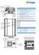
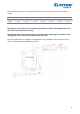
Device overview 11 6 9 10 G3 Combi Layout Pos. Description 1 ON/OFF Power switch 2 Charge current adjustment (Ampere) 3 Charger active LED – Green 4 Inverter active LED – Blue 5 Battery LED – Red 6 AC charger input 7 Positive DC voltage terminal 8 Negative DC voltage terminal 9 Data and temperature sensor connector 10 Data and Remote connector 11 Fuse for AC input (10AT, 32mm x Ø6,3mm) 12 AC output 3 12 4 5 G3 Combi LED functions Pos.
Installation The Combi/Inverter is IP21 rated and should be mounted in a dry and dust free location. Avoid mounting the device next to flammable materials. The device can be mounted vertically or horizontal by using the 4x Ø5mm holes. It is important that the airflow to and from the device is not obstructed to insure prober cooling of the device. Optimum cooling is achieved by mounting the device vertically with the DC terminals pointing down.
The table below gives the recommended minimum wire cross sections for the AC mains cables. 1012(-50) mm2 AWG mm2 1 17 AWG 1312(-80) mm2 1 17 AWG 1512(-80) mm2 1 17 AWG 2012(-100) mm2 1,5 15 AWG 1024(-30) mm2 1 17 AWG 1524(-40) mm2 1 17 AWG 2324(-50) 1,5 mm2 15 AWG Table 2 Recommended minimum AC cross section. Warning: Do not connect the AC outputs in parallel or serial. It will damage the device and is not covered by the warranty.
Operation This section describes the three different modes of operation. - Inverter mode. Energy is taken from the battery and converted to 230 Vac and delivered at the output (grey Neutrik). - Charger mode (Combi only). Energy is taken from the AC input (blue Neutrik) and passed directly through to the output. Part of the energy is converted to DC and used to recharge the battery. - Backup mode (Combi only).
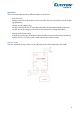
The device can also be activated by placing a voltage on the remote pin of one of the three connectors on the front of the device. This is illustrated in the schematic below. If the device is connected to a Clayton Power Lithium battery with data the inverter will by default start when the battery is activated. To change this behavior, please refer to the Clayton Power Lithium Battery User Manual. Note: if the battery is discharged the red LED will continue to light. Recharge the battery and try again.
Charger mode Activate the charger by applying 230 Vac to the AC input. Normal voltage range Extended voltage range* Minimum voltage 185 Vac 110 Vac Maximum voltage 265 Vac 265 Vac * The extended range is available if the inverter mode is not active. In the extended range the device will charge with reduced current (10A). The charge is a fully automatic 3-stage charger with IUoUo characteristic.
Charge LED When the charger is charging the green LED has the following meanings: - Green LED flashes fast: The charger delivers full charge current (with respect to charge current adjustment) and is in constant current mode. - Green LED flashes slowly: The charger is reducing the current and maintaining a constant voltage. - Green LED lights continuously: The battery is fully charged.
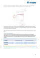
G3 Display It is possible to connect a Clayton Power G3 Display/Remote to visually get information about the device. The Display can also be used to control the operation of the device. The schematic below shows a setup where the display is able to start and stop the device with the remote pin. To get more information about the Display/Remote please refer the Clayton Power G3 Display User Manual.
LED code pattern description The following tables describe the meaning of the different LEDs The blue LED is for the inverter section The green LED is for the charger section The red LED is indicating the status of the battery.
Data connections Pin 1 RJ12 Pin1 Phoenex The connectors in position 9 and 10 are a RJ12 of type 6P6 connector.
Technical specification Inverter Model 1012 1312 1512 2012 1024 1524 2324 2336 1000W 1300W 1500W 2000W 1000W 1500W 2300W 2300W 2000W 3000W 3000W 4000W 2000W 3000W 4000W 4000W 1500W 1800W 2000W 2800W 1500W 1800W 3000W 3000W 1200W 1500W 1700W 2200W 1200W 1700W 2500W 2500W 90% 92% 90% 90% 93% 93% 92% 92% 10W 10W 15W 15W 10W 10W 15W 17W Power rating Continues output power Output power surge (1 sec) Output power surge (10 sec) Output power surge (15 min) M
Charger Model 1012-50 1312-80 1512-80 2012-100 1024-30 1524-40 2324-50 Battery Open, Sealed Lead Acid and Clayton Power Lithium Ion IUoUo Battery Types Charge characteristics Battery Temperature sensor Yes (Optional) Charge Current Max Charge current (adjustable) Charge Current reduction @ 50°C (% of max current) Charge Current reduction @ 60°C (% of max current) Charge Current reduction @ 80°C (% of max current) 0 – 50 A 0 – 80 A 0 – 80 A 0 – 100 A 0 – 30 A 0 – 40 A 0 – 50 A 0% 15 % 50