G3 COMBI MODEL: 1012-50, 1024-30, 1312-80, 1512-80, 1524-40, 2012-100, 2324-50 VERSION: 2.0 USER’S MANUAL Clayton Power Website: www.claytonpower.
Table of content 1.0 System specification 5.0 Operating the device Electrical specification inverter Mechanical specifications General features a. Mechanical dimensions Model: 1512-80 2012-100 2324-50 1.2 Mechanical dimensions Model: 1012-50 1024-30 1312-80 1524-40 2.0 Installation Environment Mounting the device 2.1 DC cables EMC Recommended cable Mounting DC cables 2.2 AC Mains cables Recommended cable 2.3 Fusing AC input AC output DC input / battery 3.0 Device layout 3.
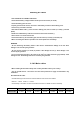
Electrical Specification Inverter MODEL 1012 1312 1512 2012 1024 1524 2324 2336 Continuous output power FTS (Full Temperature Scale) Output power surge ( 1 sec. ) Output power surge ( 10 sec. ) Output power surge ( 15 min. ) Max.
Bypass current AC input to AC output (max) 10A 10A 10A 10A 10A 10A 10A 10AT 10AT 10AT 10AT 10AT 10AT 10AT Model 1012 1312 1512 2012 1024 1524 2324 2336 IP class IP20 IP20 IP20 IP20 IP20 IP20 IP20 IP20 Dimensions of cabinet [ L x W x H ] mm 299x198,2x116 299x198,2x116 376x198,2x116 376x198,2x116 299x198,2x116 299x198,2x116 376x198,2x116 376x198,2x116 Dimensions of cabinet incl.
1.
1.
2.0 Installation Environment • The inverter (or combi) must be placed in a dry, well ventilated and dust free location. • Place the unit as close as possible to the battery in order to keep the battery cables as short as possible. • Do not place the unit in same compartment as the batteries. • Make sure that water or dust can not enter the cabinet. • Ensure that the air flow from fan is not obstructed. • Avoid mounting the device next to flammable materials.
Mounting DC cables • PAY ATTENTION TO CORRECT POLARITY! • Check that the battery voltage matches the DC input to the inverter (or combi). • Check the battery poles are clean. • Prepare good electrical contact, use brass or lead battery connectors at the battery poles. • Connect only one cable at the time. • Start with the Black cable (-).
3.0 Device layout G3 COMBI Layout Pos. 1. 2. 3. 4. 5. 6. 7. 8. 9. 10. 11. 12. 13.
3.1 External connections Pin 1 Phoenix Combicon Pin 1 RJ12 type 6p6 connector: Pin# 1 2 3 4 5 Signal - TEMPX1 6 REMOTE 1 + TEMPX1 SYNC_IN/OUT DATA Description Reserved for future use User GND ( Fused ) Reserved for future use Used in option SYNC only Single Wire Clayton Communication Connected to plus pole of the battery switches on the combi. Not connected = no influence Phoenix Combicon MSTB 2.5 / 3-ST-5.
3.2 External Wiring The two RJ12 6 pole connectors are connected parallel to each other pin to pin.
3.
4.0 Accessories No. a. b. c. COMBI Accessories List Description AC output connector, type Neutrik NAC3FCB ( Grey ) Phoenix DATA connector: MSTB 2.5 / 3-ST-5.08 - Green AC input connector , type Neutrik NAC3FCA ( Blue ) 5.0 Operating the device •The aim of this section is to give a brief overview necessary to operate the device and give some proposal how to solve most normal problems occurring during operation of the device. Information for all LED error codes can be found in section 6.
Charger section: Charge current adjust • The charge current can be adjusted by the potentiometer on the front panel top from 0A up to maximum rated charge current. • See recommended charge current table in section 5.2 Charge Current Setting for correct adjustment.
Errors charger: AC input voltage to low <185VAC (with inverter switched ON) • 1 flash by green LED Note: If the inverter is switched OFF, the charger will operate at even lower voltage than 185VAC, down to 110VAC is in this mode is accepted But with reduced charge current! AC input voltage to high >265VAC • 2 flash by green LED (rear situation!) AC input distortion • The charger can not begin charging if the input voltage is a non sine wave, or heavily distorted! • 1 flash by green LED No NTC temperature se
5.1 Load search mode • In cases where it is preferable to leave the combi switched on, and the load is periodically inactive (switched OFF) the load search mode can be activated. In this mode the combi is partly active and generate a short pulse every 2 second, if a load (>10W resistive) is detected the device switch ON automatically.
5.2 Charge Current Setting • Recommended battery capacity versus charging currents (at 20°C battery temperature) Charge Current Recommended Battery Capacity Range 15 A 75 – 150 Ah 20 A 100 – 200 Ah 25 A 100 – 250 Ah 30 A 150 – 300 Ah 40 A 200 – 400 Ah 50 A 250 – 500 Ah 60 A 300 – 600 Ah 80 A 400 – 800 Ah 120 A 600 – 1200 Ah ATTENTION! • If sealed lead acid batteries are overcharged it will result in gassing and dry-out and the battery will be destroyed.
5.3 Charging Stages • The charger is a fully automatic 3-stage charger with IUoUo characteristic. Boost charge - Fast flashing green LED • The charger will start in boost charge mode with max pre-set voltage and max charging current.
6.0 LED codes description • The Blue LED is for the Inverter section. • Green LED is for the charger section. • Red LED indicating the status of the battery. • Two or all LED can also flash together; see description of the error / status! Blue LED ON 1 Short flashes every 2. second 1 Flash 2 Flash 3 Flash 4 Flash 5 Flash Description. Inverter is running Load search mode Inverter output is overloaded Inverter temperature is too high.
7.0 Batteries WARNING! Working with batteries is dangerous! Batteries generate explosive gasses! • Therefore it is of out most importance that each time you serve equipment in the vicinity of the battery, to follow the battery instructions very accurate. Never smoke or allow a spark or a flame in the vicinity of a battery.
7.1 Maintenance batteries • Performing preventive maintenance on batteries is easy and should occur at least once a month during hot weather and every three months in cold weather. In the case of lead acid batteries the maintenance should include check the electrolyte level for non-sealed wet batteries and the State of Charge (SOC) with hydroscope measurement of specific gravity of the electrolyte and recharging the battery if necessary.
8.0 Warranty • Installation, operation, technical support, warranty and service issues should, in the first case be directed towards the outlet at which you purchased your Clayton Power inverter. CAUTION & WARNING: DO NOT USE OR ATTEMPTTO USE THIS PRODUCT UNTIL YOU HAVE READ THIS USER'S MANUAL IN ITS ENTIRETY. IMPROPER INSTALLATION OR USAGE OF THIS DEVICE MAY BE HAZARDOUS AND MAY CAUSE DAMAGE TO OTHER ELECTRICAL EQUIPMENT AND WILL VOID WARRANTY.