OPERATOR'S MANUAL CLEAN BURN MODELS: CB-1500 and CB-2500 MULTI-OIL FURNACES with CB-500 Series Burner 230 V / 50 Hz 2 20 -2 40 5 0- W z3 60H t s 10s foss Dan 64 BHO 036 pe Ty 05 7H7 Nr. FOR YOUR SAFETY DO NOT STORE GASOLINE OR OTHER FLAMMABLE VAPORS AND LIQUIDS IN THE VICINITY OF THIS OR ANY APPLIANCE!! PUBLICATION DATE: 6/1/10, Rev.
DECLARATION OF CONFORMITY Manufacturer: Clean Burn Inc . 34 Zimmerman Rd.
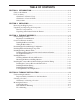
TABLE OF CONTENTS SECTION 1: INTRODUCTION .................................................................................... 1-1 Guide to this Manual ........................................................................................................ 1-1 For Your Safety... ............................................................................................................. 1-2 Guidelines for Furnace Usage ...................................................................................
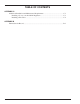
TABLE OF CONTENTS SECTION 4: FURNACE INSTALLATION (continued) Oil Tank Installation Specifications ................................................................................. 4-8 Installing the Tank Vent and Emergency Vent .......................................................... 4-9 Installing the Metering Pump ......................................................................................... 4-10 Preparing for Installation .....................................................................
TABLE OF CONTENTS SECTION 8: ADJUSTING THE DRAFT OVER FIRE ................................................ 8-1 Checking for Correct Draft Over Fire ................................................................................. 8-1 Adjusting the Barometric Damper ....................................................................................... 8-2 Solving Draft Overfire Problems .........................................................................................
TABLE OF CONTENTS APPENDIX C Additional Installation and Maintenance Requirements ................................................. C-1 Installing a Cover over the Oil/Air Regulators ......................................................... C-1 Installing a Fire Valve .............................................................................................. C-2 APPENDIX D Furnace Service Record ....................................................................................................
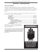
Operator's Manual: Models CB-1500 & CB-2500 (230 V / 50 Hz) SECTION 1: INTRODUCTION Guide to this Manual This manual contains all the information necessary to safely install and operate the Clean Burn CE-certified, 230 V / 50 Hz Furnace Models CB-1500 and CB-2500. Consult the Table of Contents for a detailed list of topics covered. You'll find this manual's step-by-step procedures easy to follow and understand.
Operator's Manual: Models CB-1500 & CB-2500 (230 V / 50 Hz) For Your Safety... For your safety, Clean Burn documentation contains the following types of safety statements (listed here in order of increasing intensity): • NOTE: A clarification of previous information or additional pertinent information. • ATTENTION: A safety statement indicating that potential equipment damage may occur if instructions are not followed.
Operator's Manual: Models CB-1500 & CB-2500 (230 V / 50 Hz) For Your Safety... (continued) WARNING: Never alter or modify your furnace without prior written consent of Clean Burn, Inc. Unauthorized modifications or alteration can adversely affect the proper, safe operation of your furnace. WARNING: The burner which is shipped with your Clean Burn furnace is to be used only with your furnace according to the instructions provided in this manual.
Operator's Manual: Models CB-1500 & CB-2500 (230 V / 50 Hz) For Your Safety... (continued) Guidelines for Furnace Usage • This furnace is listed for commercial and/or industrial use only; it is not listed for residential use. • This furnace is designed to burn the following fuels: • Used crankcase oil up to 50 SAE • Used transmission fluid • Used hydraulic oils • #2 fuel oil • #4 fuel oil • #5 fuel oil NOTE: Used oils may contain other substances, including gasoline, that may hinder performance.
Operator's Manual: Models CB-1500 & CB-2500 (230 V / 50 Hz) For Your Safety... (continued) Guidelines for Used Oil Tanks For the safe storage of used oil and the safety of persons in the vicinity of the used oil supply tank, ensure that your tank installation adheres to the following safety guidelines: • • • • The tank installation must meet all national and local codes. Consult your local municipal authorities for more information as necessary.
Operator's Manual: Models CB-1500 & CB-2500 (230 V / 50 Hz) For Your Safety... (continued) Safety Labels Following are the locations and descriptions of all labels on your CB-1500 or CB-2500 furnace. The following illustrations show the location of ALL labels on your furnace. Please note that some labels denote model number, model description, etc. while others contain important safety messages.
Operator's Manual: Models CB-1500 & CB-2500 (230 V / 50 Hz) For Your Safety...
Operator's Manual: Models CB-1500 & CB-2500 (230 V / 50 Hz) For Your Safety... (continued) CB-1500/CB-2500 Furnace Cabinet Safety Labels CLEAN BURN, INC. CLEAN BURN, INC. LEOLA, PENNSYLVANIA (USA) LEOLA, PENNSYLVANIA (USA) CB 1500 CB 2500 BTU/HR (KW) 250,000 73 1.1 BTU/HR (KW) 150,000 44 3.9 14.0 1.0 1.3 0.1 1.7 6.4 18.0 1.2 3.5 0.24 1.1 4.0 14.0 1.0 2.0 0.1 1.7 6.4 16.0 1.1 4.0 0.28 1.1 4.0 14.0 1.0 2.0 0.1 1.7 6.4 17.0 1.2 4.0 0.28 1.1 4.0 16.0 1.1 2.
Operator's Manual: Models CB-1500 & CB-2500 (230 V / 50 Hz) For Your Safety...
Operator's Manual: Models CB-1500 & CB-2500 (230 V / 50 Hz) 1-10
Operator's Manual: Models CB-1500 & CB-2500 (230 V / 50 Hz) SECTION 2: UNPACKING Before assembling your furnace, you must accomplish the following activities described in this section: • Removing the Shipping Crate • Unpacking and Inspecting All Components Removing the Shipping Crate NOTE: Remove the shipping crate prior to assembly and installation of the furnace. DO NOT use the crate as a platform for furnace installation! 1. Carefully remove the top boards of the shipping crate.
Operator's Manual: Models CB-1500 & CB-2500 (230 V / 50 Hz) Unpacking Items Packed Inside the Furnace To unpack the items packed inside the furnace cabinet (in the combustion chamber), you will need to open the combustion chamber door. 1. 2. 3. Remove the four nuts and washers which hold the combustion chamber door closed. Set the nuts and washers aside in a safe place for later re-installation after the target has been installed (Section 3). Carefully swing the combustion chamber door open.
Operator's Manual: Models CB-1500 & CB-2500 (230 V / 50 Hz) SECTION 3: FURNACE ASSEMBLY Understanding Assembly Assembling your Clean Burn Furnace includes the following steps: (1) Installing the Blower Assembly (2) Installing the Hot Air Discharge Components (3) Installing the Energy Retention Disc (4) Installing the Burner (5) Installing the Connector Block, Oil Line Tubing, and Air Line Tubing Clean Burn recommends that you review all assembly procedures before proceeding, paying careful attention to saf
Operator's Manual: Models CB-1500 & CB-2500 (230 V / 50 Hz) "ALL THREAD" RODS COUPLINGS FOR "ALL THREAD" RODS JUNCTION BOX BURNER CABLE 4 BURNER MOUNTING BRACKET THROAT Danfoss Type BHO 64 Nr. 05 7H7036 220-2 40V 5 0-60Hz 3W ts 10s R.H.
Operator's Manual: Models CB-1500 & CB-2500 (230 V / 50 Hz) Installing the Blower Assembly 1. 2. 3. 4. 5. Refer to Figures 3B and 3C. Remove the blower stabilizer brackets as shown in Figure 3B. (These braces, which are installed at the factory, are designed to keep the blower in proper position during shipping. Note that these braces are provided on CB-2500 blower assemblies ONLY; CB-1500 blower assemblies do not require these special shipping braces.
Operator's Manual: Models CB-1500 & CB-2500 (230 V / 50 Hz) Installing the Blower Assembly (continued) Black Motor Lead − Orange Wire White Motor Lead − White Wire Brown Motor Leads − Capacitor Green Wire − Ground Screw Note: CB-1500 is shown; CB-2500 Junction Box and Motor are mounted on the opposite side of the blower. I89017 Figure 3C - Blower Installed on Furnace Cabinet Wiring the Blower Motor WARNING: Make sure the main power to the furnace is turned OFF before wiring the blower motor.
Operator's Manual: Models CB-1500 & CB-2500 (230 V / 50 Hz) Determining the Hot Air Discharge Configuration Before proceeding with the assembly of your furnace, it is important to determine the configuration of the air discharge for your furnace. There are three configurations to consider for the CB-2500 and two possible configurations for the CB-1500: (1) Unit Heater CB-1500 and CB-2500 Furnace with blower assembly for FREE AIR applications.
Operator's Manual: Models CB-1500 & CB-2500 (230 V / 50 Hz) Determining the Hot Air Discharge Configuration (continued) Air Flow - Cubic Meters per Minute (CMM) or Cubic Feet per Minute (CFM) and Static Pressure (SP) Specifications CB-1500 Air Discharge Louvers Mounted on Furnace Air Discharge Louvers Removed With Ductwork Installed on Furnace Free Air* 0.06 kPa* (0.
Operator's Manual: Models CB-1500 & CB-2500 (230 V / 50 Hz) Installing the Hot Air Discharge Components (continued) 1. 2. 3. 4. Refer to Figures 3D and 3E. Determine the desired air flow discharge pattern. Note that the CB-1500 is supplied with (2) louver sections and (4) blank cover panels. The CB-2500 is supplied with (3) louver sections and (3) blank cover panels. Air discharge openings are: (1) on each side of the furnace, and (1) on the bottom of the furnace.
Operator's Manual: Models CB-1500 & CB-2500 (230 V / 50 Hz) Installing the Hot Air Discharge Components (continued) Louvers split between two side openings, showing left and right side views of same furnace NOTE: When louver panels are "split" between two sides, make sure the louvers are installed in the upper half of each side air discharge opening as shown here.
Operator's Manual: Models CB-1500 & CB-2500 (230 V / 50 Hz) Installing the Energy Retention Disc Installing the Energy Retention Disc at the Back of the Combustion Chamber ATTENTION: DO NOT fire your furnace without the Energy Retention Disc in place, or combustion chamber damage will occur. Handle the Energy Retention Disc carefully to avoid damaging it. 1. 2. 3. Refer to Figure 3A to review the proper positioning of the Energy Retention Disc.
Operator's Manual: Models CB-1500 & CB-2500 (230 V / 50 Hz) Installing the Burner (continued) BURNER NOZZLE NOZZLE IS STAMPED WITH SIZE ON FLAT OF NOZZLE HEAD SIDE VIEW − AA 5 mm (3/16") GAP BETWEEN ELECTRODES & NOZZLE 3X CRITICAL DIMENSION: NOZZLE MUST BE 3 mm (1/8") AHEAD OF THE DISK. NOZZLE MUST NOT BE BEHIND THE DISK.
Operator's Manual: Models CB-1500 & CB-2500 (230 V / 50 Hz) Installing the Burner (continued) Mounting the Burner on the Hinge Bracket ATTENTION: Burner tube components (e.g. electrodes and retention head) are factory set. Handle the burner with extreme care so that burner components are not damaged. 1. Remove the nut from the mounting flange of the furnace cabinet, and set it aside for later use. 2. Lift the burner into position so that it is mounted on the hinge bracket on the furnace cabinet. 3.
Operator's Manual: Models CB-1500 & CB-2500 (230 V / 50 Hz) Installing the Connector Block, Oil Line Tubing, and Air Line Tubing ATTENTION: DO NOT use teflon tape on any fittings. Teflon tape residues will plug vital burner components. Installing the Connector Block on the Furnace Door OIL LINE 1. 2. 3. Refer to Figure 3G. Use the two (2) bolts to install the aluminum connector block onto the furnace cabinet. Remove and discard the red caps and plugs from the fittings and ports on the connector block.
Operator's Manual: Models CB-1500 & CB-2500 (230 V / 50 Hz) Installing the Connector Block, Oil Line Tubing, and Air Line Tubing (continued) Installing the Oil Line Tubing (continued) 5. 6. Make sure that the curl in the oil line is positioned as shown in Figure 3G so that the burner can swing open correctly. Install the oil line tubing and tighten the nuts on the compression fittings. DO NOT overtighten these fittings to avoid damaging the ferrules.
Operator's Manual: Models CB-1500 & CB-2500 (230 V / 50 Hz) Locking the Burner Into Firing Position 1. 2. 3. 4. Swing the burner into firing position. Install and tighten the lock-down nut on the mounting plate bolt to secure the burner in its firing position. Plug the burner electrical cable into the receptacle on the top of the burner housing. Tighten the locking ring to secure the electrical cable. PLUG ON CAM LOCK CABLE NOTE: Be sure to properly align the plug when plugging it into the receptacle.
Operator's Manual: Models CB-1500 & CB-2500 (230 V / 50 Hz) SECTION 4: FURNACE INSTALLATION Understanding Installation Installing your Clean Burn furnace is a multi-step process which includes: (1) Selecting a Location (2) Mounting the Furnace (3) Oil Tank Installation Specifications (review) (4) Installing the Metering Pump (5) Wiring the Furnace and Pump (6) Installing the Oil Lines (7) Installing the Compressed Air Line (8) Installing the Stack (9) Installing the Wall Thermostat (10) Inspecting the Inst
Operator's Manual: Models CB-1500 & CB-2500 (230 V / 50 Hz) Important Safety Guidelines for Safe Installation (continued) The Environmental Protection Act 1990, Part 1: Processes prescribed for air pollution control by local enforcing authorities PG1/1 (95). Secretary of State's Guidance: Waste Oil Burners, less than 0.4 MW net rated thermal input. November 1995 (Appendix A of OFTEC OFSA 103). OFTEC Guidelines: Document OFG100 for externally serviced oil fired appliances.
Operator's Manual: Models CB-1500 & CB-2500 (230 V / 50 Hz) (2 FT) NOTE: THE LAST STACK SECTION SHALL EXTEND AT LEAST 92 cm (3 FT) ABOVE THE HIGHEST POINT AT WHICH IT COMES IN CONTACT WITH THE ROOF, AND AT LEAST 61 cm (2 FT) HIGHER THAN ANY RIDGE, PARAPET OR ROOF STRUCTURE WITHIN 3 m (10 FT) OF IT. 61 cm WARNING! NEVER LOCATE A STACK JOINT INSIDE WALLS OR IN A JOIST SPACER.
Operator's Manual: Models CB-1500 & CB-2500 (230 V / 50 Hz) NON−RESTRICTIVE "CLASS A" STACK CAP "CLASS A" STACK INSULATED STACK WITH STAINLESS STEEL LINER WARNING! OUTSIDE STACK AND STACK PENETRATIONS THROUGH CEILING, ROOF OR SIDEWALL MUST BE "CLASS A" FOR FIRE SAFETY AND TO MAINTAIN PROPER DRAFT WARNING! MAKE SURE TO INSTALL THE PROPER ROOF SUPPORT SYSTEM TO SAFELY SUPPORT THE STACK EXTERIOR SINGLE WALL STACK DOES NOT MEET CODE.
Operator's Manual: Models CB-1500 & CB-2500 (230 V / 50 Hz) Selecting a Location Guidelines for Selecting a Location The location you select for your furnace must allow the following: • Unobstructed, even heat distribution. • Safe, easy access for servicing. • Unobstructed passage for shop vehicles and equipment. • Proper clearances from combustibles. Verify according to your local safety codes. • Adequate combustion air per local codes. • Proper stack installation.
Operator's Manual: Models CB-1500 & CB-2500 (230 V / 50 Hz) Selecting a Location (continued) 5 cm (2") REAR 31 cm (12") TOP 46 cm (18") OTHER SIDE (WITHOUT AIR DISCHARGE) 50 -60 46 cm (18") CHIMNEY CONNECTOR 3W Hz 1 0s ts 40 2 2 0-2 oss Danf 64 BHO 6 pe 7 H703 Ty 05 Nr.
Operator's Manual: Models CB-1500 & CB-2500 (230 V / 50 Hz) Mounting the Furnace (continued) Raised Platform Mounting WARNING: To prevent serious personal injury, make sure the platform is designed to safely bear the weight of the furnace and allow safe servicing of furnace components. The platform must be constructed of non-combustible materials (e.g. steel) and must be securely anchored to an adjacent wall. 1. Danfo ss Typ e BHO 6 4 Nr.
Operator's Manual: Models CB-1500 & CB-2500 (230 V / 50 Hz) Oil Tank Installation Specifications Ensure that your tank installation adheres to the following safety guidelines as stated here and in Section 1 of this manual. The tank safety label (shown at right) also summarizes these important specifications for tank installation and usage. If you do not have a copy of this label, please contact your Clean Burn dealer for a copy, which is to be affixed directly to your used oil supply tank.
Operator's Manual: Models CB-1500 & CB-2500 (230 V / 50 Hz) Oil Tank Installation Specifications (continued) TANK VENT KITS AVAILABLE FROM CLEAN BURN: CB Part # 70380 − 4" Tank Vent Kit (2) elbows (2) 6" nipples (1) mushroom cap vent (1) emergency vent PRESSURE PRESSURE LINE RELIEF OIL LINE BACK TO THE TANK PUMP MUSHROOM CAP VENT STEEL PIPE (USER SUPPLIED) SUCTION LINE ASSEMBLY FUNNEL WITH BALL VALVE EMERGENCY VENT CHECK VALVE FILTER SCREEN CLEAN−OUT (TANK DRAIN) Figure 4F - Typical Metering Pump I
Operator's Manual: Models CB-1500 & CB-2500 (230 V / 50 Hz) Installing the Metering Pump Preparing for Installation Before starting installation of the metering pump, review Figures 4G, 4H, and 4I to become familiar with the metering pump components. You will also need to accomplish the following activities: • Verify that you have the proper metering pump for your furnace (note the specific gear motor part numbers shown in Figure 4H).
Operator's Manual: Models CB-1500 & CB-2500 (230 V / 50 Hz) # 2 3 4 5 6 7 8 9 10 11 12 13 14 15 16 17 18 19 20 21 22 23 24 25 26 27 28 29 30 31 PART # see chart 11322 32037 N/A 32140 N/A 32141 32526 32475 32467 32210 32336 32123 32127 32430 32446 32429 32137 32142 32062 32443 32141 32140 32139 32442 32021 32061 32445 32474 32335 DESCRIPTION GEARMOTOR MOUNT − METER PUMP 1/8 NPT X 1/4 TUBE COMPRESSION FITTING 1/4 COPPER OR ALUM. TUBING LONG NUT 1/2 1/2 COPPER OR ALUM. TUBING FLARED TUB.
Operator's Manual: Models CB-1500 & CB-2500 (230 V / 50 Hz) Installing the Metering Pump (continued) Alternate Mounting: Horizontal Positioning ATTENTION: If the metering pump is to be mounted horizontally or on a bracket as shown in Figure 4I, the pump head must be rotated counterclockwise so that it is aligned in a horizontal position. The gauge arrow on the pump head must point up, or the pump will not prime. 1. 2. 3. 4. 5. Refer to Figures 4H and 4I. Remove the two pump mounting bolts.
Operator's Manual: Models CB-1500 & CB-2500 (230 V / 50 Hz) Wiring the Furnace and Pump WARNING: To avoid electrical shock, make sure that power to the furnace is turned OFF before connecting any wires. A licensed electrician should install all wiring to your furnace. All wiring must be in accordance with national and local codes. Properly size all wires and use electrical conduit for all electrical lines.
Operator's Manual: Models CB-1500 & CB-2500 (230 V / 50 Hz) Installing the Suction Oil Line Components ATTENTION: It is critical that you adhere to the following specifications for suction oil line installation (oil line from the tank to the pump). If these specifications are not met, the metering pump will not function correctly and the burner will shut down on reset.
Operator's Manual: Models CB-1500 & CB-2500 (230 V / 50 Hz) Installing the Suction Oil Line Components (continued) (e.) Prepare the canister filter for installation (continued): • Install this assembly into one side of the 1/2" brass tee. • Install the assembled 1/2" tee into the 3/4" x 1/2" brass bushing, which is installed in the inlet port of the canister filter. Make sure that the 1/2" flare adapter is pointing down.
Operator's Manual: Models CB-1500 & CB-2500 (230 V / 50 Hz) 2. Install the suction oil line (from the the tank to the canister filter): a. Refer to Figures 4H and/or 4J. b. Prepare a piece of 1/2" O.D. copper tubing (user-supplied) which will function as the pick-up line from the tank to the canister filter. This copper tubing must have the following specification • The tube must be one continuous piece of 1/2" O.D. copper tubing with no kinks or fittings.
Operator's Manual: Models CB-1500 & CB-2500 (230 V / 50 Hz) Installing the Pressure Relief Oil Line Back to the Tank ATTENTION: It is critical that you adhere to the following specifications for plumbing the pressure relief back to the tank. The metering pump requires the installation of a pressure relief oil line back to the tank that you are pulling oil from as shown in Figures 4H, 4J, and 4K.
Operator's Manual: Models CB-1500 & CB-2500 (230 V / 50 Hz) Installing the Pressure Oil Line Components ATTENTION: It is critical that you adhere to the following specifications for pressure oil line installation (oil line from the pump to the furnace); if these specifications are not met, the metering pump will not function correctly and the burner will shut down on reset. The parameters for pressure oil line installation are: Length of Pressure Line Line Size Up to 30 m (100') 10 mm (3/8") O.D.
Operator's Manual: Models CB-1500 & CB-2500 (230 V / 50 Hz) Installing the Stack WARNING: Inappropriate stack materials or improper stack design/installation can adversely affect the proper, safe operation of your furnace. Contact your Clean Burn dealer to purchase the proper stack components for your furnace. Stack designs are generally classified as follows: (1) "Class A" stack through the ceiling of the building. Refer to Figure 4L.
Operator's Manual: Models CB-1500 & CB-2500 (230 V / 50 Hz) Installing the Stack (continued) "CLASS A" STACK COMPONENTS INSULATED STACK WITH A STAINLESS STEEL LINER WARNING! ENSURE PROPER CLEARANCES BETWEEN STACK COMPONENTS AND COMBUSTIBLES PER ALL APPLICABLE CODES.
Operator's Manual: Models CB-1500 & CB-2500 (230 V / 50 Hz) Installing the Stack (continued) "CLASS A" STACK CAP − NON−RESTRICTIVE TYPE TO ALLOW FREE FLOW OF THE STACK GASES 3 m (10’) WARNING! MAKE SURE TO INSTALL THE PROPER WALL SUPPORT SYSTEM TO SAFELY SUPPORT THE STACK "CLASS A" STACK PENETRATION AND CLEAN−OUT TEE 6 mm (1/4") HOLE FOR SETTING DRAFT. ADJUST BAROMETRIC DAMPER FOR −.04 W.C. DRAFT AT BREECH −0.02 W.C. DRAFT OVERFIRE IS ESSENTIAL FOR PROPER FURNACE OPERATION.
Operator's Manual: Models CB-1500 & CB-2500 (230 V / 50 Hz) Installing the Interior Stack WARNING: Single wall stack components may be used only for those portions of the stack which are located inside your building and away from any fire/burn hazards. 1. 2. Install the single wall stack with proper clearances from combustibles. Also ensure that the stack is located a safe distance from all shop personnel.
Operator's Manual: Models CB-1500 & CB-2500 (230 V / 50 Hz) Installing the Stack Penetration WARNING: When running the stack through your ceiling, roof, or sidewall, you must use a proper insulated "Class A" stack penetration with a stainless steel liner. DO NOT run single-wall stack through your ceiling, roof or sidewall. Single-wall penetrations do not meet safety codes and may create a fire hazard. Never locate a stack joint inside walls or in a joist spacer.
Operator's Manual: Models CB-1500 & CB-2500 (230 V / 50 Hz) Installing the Optional Draft Inducer (continued) "CLASS A" STACK (DOUBLE−WALL INSULATED ALL−FUEL STACK ) 1.5 m − 2.5 m (5’ − 8’) NOTE: INSTALL DRAFT INDUCER IN LAST SECTION OF VERTICAL STACK TO POSITION DRAFT INDUCER AWAY FROM FURNACE BREECH SO THE MOTOR DOES NOT OVERHEAT. THIS ALSO REDUCES ASH ACCUMULATION IN THE DRAFT INDUCER. DRAFT ADJUSTMENT PLATE DO NOT MOUNT THE DRAFT INDUCER IN THE HORIZONTAL STACK NEAR THE FURNACE BREECH.
Operator's Manual: Models CB-1500 & CB-2500 (230 V / 50 Hz) Installing the Optional Draft Inducer (continued) Installing the Draft Inducer WARNING: Turn OFF the main power to the furnace before proceeding with the installation of the draft inducer. ATTENTION: It is very important to install the draft inducer on a vertical section of stack to isolate the inducer from excessive heat and ash buildup.
Operator's Manual: Models CB-1500 & CB-2500 (230 V / 50 Hz) 4-26
Operator's Manual: Models CB-1500 & CB-2500 (230 V / 50 Hz) SECTION 5: METERING PUMP PRIMING Understanding Metering Pump Priming Preparing your Clean Burn furnace for operation begins with priming the metering pump. The procedures in this section must be performed in sequence without interruption to properly prime the pump.
Operator's Manual: Models CB-1500 & CB-2500 (230 V / 50 Hz) Priming the Metering Pump ATTENTION: The priming process must be done precisely as described in this procedure to ensure that all air is thoroughly bled from the system. Failure to bleed all air from the system will result in repeated burner shutdowns on reset. 1. 2. 3. 4. 5. 6. 7. Refer to Figure 5A. Remove the 1/4" NPT plug from the side of the pump head, and set it aside. Remove the 1/2" brass cap from the 1/2" brass nipple.
Operator's Manual: Models CB-1500 & CB-2500 (230 V / 50 Hz) Priming the Metering Pump (continued) 8. Activating the Pump NOTE: The furnaces features a priming switch which is mounted on the right-hand side of the electrical junction box on the front of the furnace cabinet. The priming switch has two positions: • PRIME: This is used only for pump priming. When the switch is in the PRIME position, the pump circuit is activated for priming.
Operator's Manual: Models CB-1500 & CB-2500 (230 V / 50 Hz) Priming the Metering Pump (continued) 9. 10. 11. 12. 13. 14. 15. 16. 17. Run the pump until a solid stream of oil flows from the pump bleeder. This will bleed all air out of the suction line, oil filter and pump head. ATTENTION: For the metering pump to operate correctly, it is very important that the system is entirely full of oil and all air is bled out. The burner will shut down if there is any air in the system.
Operator's Manual: Models CB-1500 & CB-2500 (230 V / 50 Hz) Vacuum Testing the Oil Pump (continued) 5. If there are no suction leaks, the system will hold vacuum. NOTE: It is acceptable for the vacuum to drop one to five inches within one minute as the seal in the pump seats. The vacuum should then hold steady for 15 minutes. ATTENTION: If the vacuum drops more than one to five inches within the first minute, there is one or more leaks somewhere between the pump and the ball valve.
Operator's Manual: Models CB-1500 & CB-2500 (230 V / 50 Hz) 5-6
Operator's Manual: Models CB-1500 & CB-2500 (230 V / 50 Hz) SECTION 6: STARTING AND ADJUSTING THE BURNER Understanding Burner Startup and Adjustment Starting and adjusting the burner involves a series of separate procedures which must be accomplished in sequence without interruption. Review all the procedures before attempting burner startup and adjustment, paying careful attention to safety information statements. Preparing the Burner for Startup 1. 2. 3. 4. Turn the switch on the wall thermostat OFF.
Operator's Manual: Models CB-1500 & CB-2500 (230 V / 50 Hz) Preparing the Burner for Startup (continued) NOTE: The air gauge will not show any pressure until the burner starts. Before starting the burner for the first time, it is very important to turn the air regulator completely OFF as described. 6. Initial Adjustment of the Combustion Air Band: WARNING: The combustion air band must be properly adjusted to ensure that the burner ignites and burns correctly.
Operator's Manual: Models CB-1500 & CB-2500 (230 V / 50 Hz) Starting the Burner 1. Turn the switch on the wall thermostat to HEAT and adjust the thermostat setting above room temperature to start the burner. NOTE: If the burner refuses to start, review the Preparing the Burner for Startup procedure.
Operator's Manual: Models CB-1500 & CB-2500 (230 V / 50 Hz) Starting the Burner (continued) 4. 5. 6. 7. Check the flame length after the burner has fired for 15 minutes. Tighten the locking nut on the air regulator. Fine Tuning the Combustion Air Band: NOTE: The initial setting of the combustion air band may require additional adjustment. • Refer to Figure 6A to identify the combustion air band location on the burner. • Observe the flame. The flame should be yellow-white with sharp tips and no "sparkles.
Operator's Manual: Models CB-1500 & CB-2500 (230 V / 50 Hz) SECTION 7: RESETTING THE FURNACE AND BURNER Understanding Furnace/Burner Shutdowns When troubleshooting furnace/burner shutdown situations, Clean Burn recommends the following sequence of actions: • Follow the procedure for Resetting the Oil Primary Control provided in this section. • Review the material on the following page about the safety switches to determine if the furnace is shut down on high limit.
Operator's Manual: Models CB-1500 & CB-2500 (230 V / 50 Hz) The Blower/Fan Switch The CB-1500/CB-2500 furnaces feature an F-180 blower/fan switch (normally open) which is surface mounted at the front of the combustion chamber (see Figure 7B). The blower/fan switch senses the temperature of the combustion chamber as the burner is firing. When the combustion chamber reaches the proper temperature, the blower/fan switch closes and sends power to the blower motor to turn ON the blower.
Operator's Manual: Models CB-1500 & CB-2500 (230 V / 50 Hz) CLEAN−OUT BREECH COMBUSTION CHAMBER CLEAN−OUT CAP 33288 L−290 HI LIMIT AUXILIARY SWITCH (AUTO RESET) (33230) F−180 SURFACE MOUNT FAN SWITCH BLACK & TAN WIRE FROM TERMINAL BLOCK RED & TAN WIRE LINKS THE 2 SWITCHES IN SERIES (33390) L−200 HI LIMIT NC RED & TAN WIRE TO BURNER RED & TAN WIRE FROM TERMINAL BLOCK BLACK AND TAN WIRE TO TERMINAL BLOCK Figure 7B - Locating the Fan Switch and Hi-Temp Limit Switches 7-3 I88947
Operator's Manual: Models CB-1500 & CB-2500 (230 V / 50 Hz) 7-4
Operator's Manual: Models CB-1500 & CB-2500 (230 V / 50 Hz) SECTION 8: ADJUSTING THE DRAFT OVERFIRE Understanding the Importance of Draft Draft in the furnace is created as the hot combustion gases rise up the stack, creating a negative pressure inside the stack and the furnace. This negative pressure is measured as inches of water column (W.C.) of draft. A proper draft overfire of -.02 to -.04 w.c.
Operator's Manual: Models CB-1500 & CB-2500 (230 V / 50 Hz) Adjusting the Barometric Damper NOTE: If the draft overfire is not in the -.02 to -.04 w.c. range, it is necessary to adjust the barometric damper. 1. 2. 3. 4. 5. Before starting the burner, turn the weight on the flapper COUNTERCLOCKWISE until the flapper remains closed. This will ADJUST THIS WEIGHT provide maximum draft for the furnace. TO OBTAIN PROPER Follow the directions in Section 6 to start DRAFT OVERFIRE and adjust the burner.
Operator's Manual: Models CB-1500 & CB-2500 (230 V / 50 Hz) Understanding the Effect of Exhaust Fans on Draft Any type of exhaust fan, paint booth, or exhaust system in a building will create negative pressure in the building unless there is a source of make-up air (i.e. fresh air which enters the building and replaces the air removed by the exhaust fans.) Refer to Figure 8C on the following page.
Operator's Manual: Models CB-1500 & CB-2500 (230 V / 50 Hz) BACKDRAFT EXHUST FAN CREATES BACKDRAFT IN STACK AND SUCKS COMBUSTION GASES DOWN THE STACK AND BACK INTO THE FURNACE 50220- Hz 60 ts 3W 10s 240 o ss 4 6 D anf 36 BHO e Typ. Nr To arrive at proper draft measurements be sure that all fans within the building are running while adjusting the draft to final levels! 057H70 OIL SPRAY AND HEAT IS FORCED BACK AGAINST THE BURNER AND RESULTS IN OIL FOULED ELECTRODES AND RETENTION HEAD.
Operator's Manual: Models CB-1500 & CB-2500 (230 V / 50 Hz) Installing a Make-up Air Louver Exhaust Fans and Make-up Air Louvers When exhaust fans are operated in tight buildings, there is little or no source of fresh air to replace the air removed from the building by the exhaust fan. This results in negative pressure (vacuum) in the building which creates severe backdraft problems at the furnace.
Operator's Manual: Models CB-1500 & CB-2500 (230 V / 50 Hz) Installing a Make-up Air Louver (continued) CALCULATED OPENING SIZE cm2 in2 0 – 528 0 – 82 529 – 836 83 – 130 837 – 1,445 131 – 224 1,446 – 1,923 225 – 299 1,924 – 2,390 300 – 370 2,391 – 3,166 371 – 490 3,167 – 4,769 491 – 739 4,770 – 7,150 740 – 1109 7,151 – 9,182 1,110 – 1,424 9,183 – 12,355 1,425 – 1,915 12,356 – 15,499 1,916 – 2,400 15,500 – 19,650 2,401 – 3,045 REQUIRED LOUVER / GRILL SIZE cm in 25 x 25 10 x 10 30 x 30 12 x 12 41 x 41 16 x
Operator's Manual: Models CB-1500 & CB-2500 (230V / 50 Hz) SECTION 9: MAINTENANCE Understanding Maintenance Servicing your Clean Burn furnace in a timely manner is very important to keep your furnace running in peak condition. Just as an automobile requires periodic maintenance such as oil changes, engine tune-ups, etc. your Clean Burn furnace also requires regularly scheduled service.
Operator's Manual: Models CB-1500 & CB-2500 (230V / 50 Hz) Periodic Burner Inspection Following initial start up of the burner, you should inspect the operation of the burner periodically--ideally on a monthly basis. Doing so ensures that the system is functioning efficiently and safely.
Operator's Manual: Models CB-1500 & CB-2500 (230V / 50 Hz) Cleaning the Canister Filter ATTENTION: Never operate your furnace with more than 10" HG of vacuum on the suction side of the pump. High vacuum separates air from the oil and results in erratic burner operation. The following protective gear should be worn when cleaning the filter: • Rubber gloves • Safety goggles 1. 2. 3. 4. 5. 6. 7. 8. 9. Close the ball valve adjacent to the filter. Position a container under the filter.
Operator's Manual: Models CB-1500 & CB-2500 (230V / 50 Hz) Servicing the Metering Pump 1. 2. 3. 4. 5. 6. Refer to Figure 9C. Remove the pump head cover (part 1). Remove the screen (part 2) and wash it. Remove and discard the used gasket (part 3). Install a new gasket (Clean Burn Part #32422). Replace the screen and pump head cover.
Operator's Manual: Models CB-1500 & CB-2500 (230V / 50 Hz) Cleaning Ash From the Furnace NOTE: The maintenance interval for cleaning ash from the furnace is approximately 700 hours of operation as indicated on the hour meter on the burner (refer to the servicing intervals at the beginning of this chapter). Be sure to clean the ash from your furnace at least twice during the heating season. Your furnace may require more frequent clean out of the ash due to contaminants in the oil or heavy use.
Operator's Manual: Models CB-1500 & CB-2500 (230V / 50 Hz) Cleaning Ash From the Furnace (continued) 1. 2. 3. Ensure that power has been turned OFF, and all "hot" components have been allowed to cool sufficiently. (Allow at least one hour for the Energy Retention Disc to cool.) Clean the ash from the stack components: a. Brush accumulated ash from the stack cap. b. Lightly tap the stack components to loosen the ash. c. Allow ash and dust to settle in the elbow on the stack.
Operator's Manual: Models CB-1500 & CB-2500 (230V / 50 Hz) Cleaning Ash From the Furnace (continued) k. Re-install the furnace components: Swing the clean-out door shut; install and tighten the lock-down nuts so that the door seals properly. Re-install the air and oil lines on the bottom of the connector block. NOTE: You may need to bleed air from the oil line before starting the burner. See Section 5 for the pertinent instructions.
Operator's Manual: Models CB-1500 & CB-2500 (230V / 50 Hz) Cleaning the Tank DO NOT allow water, sludge, or other debris to accumulate in your oil supply tank to the point that noncombustible or harmful materials are drawn into the pump or burner. Drain water and sludge from the bottom of your tank at least once a year, and more frequently with water accumulation. NOTE: If your used oil tank has not been cleaned on a regular basis, a considerable amount of sludge, etc.
Operator's Manual: Models CB-1500 & CB-2500 (230 V / 50 Hz) SECTION 10: TROUBLESHOOTING The following charts and tables are provided for reference in troubleshooting any difficulties encountered in furnace operation and adjustment. • The Flow Chart outlines the proper sequence of events in furnace operation -- use this chart to help diagnose where a problem may be occurring. • More specific troubleshooting information is provided in the Troubleshooting Tables following the flow charts.
10-2 Air sensing switch receives power from centrifugal switch. Air sensing switch closes as it receives more than 0.7 bar (10 psi) of air pressure. Blower switch senses OFF temperature of 71 °C (160 °F) and Blower switch opens. Warm air delivered to heated area. Hour meter starts. Yellow indicator light ON. Pump circuit starts oil pump. Blower stops running. Blower switch sends power to motor, and blower starts.
Operator's Manual: Models CB-1500 & CB-2500 (230 V / 50 Hz) PROBLEM Burner won’t run at all and Green power light is NOT ON. Burner won’t run at all and Green power light is ON. POSSIBLE CAUSE POSSIBLE ACTION(S) 1. 2. Circuit breaker/main switch open. Fuse/breaker blown. 1. 2. 3. 3. 1. 2. Burner cable is damaged or not plugged in properly. Oil primary control has shut down on safety reset. Wall thermostat is not operating. 3. Heater block is not heating up. 3. 4.
Operator's Manual: Models CB-1500 & CB-2500 (230 V / 50 Hz) PROBLEM Burner ignites, but will not stay running and Burner shuts off on reset within 15 seconds. Burner ignites and runs properly, but the burner shuts off on reset periodically (e.g. the burner goes off on reset during the night and requires resetting in the morning). POSSIBLE CAUSE POSSIBLE ACTION(S) 1. There is a fuel delivery problem. 1. 2. The cad cell is dirty. 2. 3. Cad cell wires are loose. 3. 4.
Operator's Manual: Models CB-1500 & CB-2500 (230 V / 50 Hz) PROBLEM Burner ignites and Burner shuts off on reset sometime later during the day or night. POSSIBLE CAUSE POSSIBLE ACTION(S) 1. There is air in the fuel supply. 1. 2. 2. 3. The primary control is not receiving the proper µA signal from the cad cell. There is insufficient air pressure. 4. The heater block is cold. 4. 5. The electrodes are fouled. 5. 10-5 3. Prime the pump.
Operator's Manual: Models CB-1500 & CB-2500 (230 V / 50 Hz) PROBLEM Pump will not prime and Pump motor is running. POSSIBLE CAUSE POSSIBLE ACTION(S) 1. There is a leak(s) in the suction line. 1. 2. 2. 3. The pump is not installed so it will fill with oil during the priming process. The pump gears are dry. 4. The pump seal is damaged. 4. 5. The ball valve is closed. 5. 6. The canister filter is dirty. 6. 7. The check valve is dirty. 7. 8. The pump is damaged or worn out. 8. 10-6 3.
Operator's Manual: Models CB-1500 & CB-2500 (230 V / 50 Hz) PROBLEM POSSIBLE CAUSE POSSIBLE ACTION(S) 1. There is NO power on t he p ump circuit from th e burner. 1. 2. The pu mp moto r has shu t off o n th ermal o ve rloa d. 2. Blower motor runs all the time. 1. Blower motor circu it is wire d inco rrectly. 1. Blower motor will not run. 1. The blower mo tor is not wired correctly. 1. 2. The Blower / Fan switch is d efective.
Operator's Manual: Models CB-1500 & CB-2500 (230 V / 50 Hz) 10-8
Operator's Manual: Models CB-1500 & CB-2500 (230 V / 50 Hz) APPENDIX A Detailed Furnace Specifications Furnace Technical Specifications Furnace Model CB-1500 CB-2500 Input 44 KW @ 4 LTR/HR (150,000 @ 1.1 GPH) 77 KW @ 6.4 LTR/HR (250,000 @ 1.7 GPH) Listed Fuels #2, #4, and #5 fuel oils used crankcase oil #2, #4, and #5 fuel oils used crankcase oil used ATF used hydraulic oil used ATF used hydraulic oil Cabinet Dimensions (L x W x H) 1320 x 673 x 673 mm (52 x 26.5 x 26.
Operator's Manual: Models CB-1500 & CB-2500 (230 V / 50 Hz) Burner Technical Specifications Burner CB-500-CE-5W Ignition Transformer Danfoss (14,000 Volts) Nozzle Delavan 9-5 Burner Motor 1/10 HP 2800 RPM with centrifugal switch Burner Motor Rotation CCW shaft end Compressed Air Requirements 0.06 CMM @ 1.7 Bar (2.
Operator's Manual: Models CB-1500 & CB-2500 (230 V / 50 Hz) Furnace Dimensions FURNACE DIMENSIONS NOTE: MEASUREMENT FROM BOLT CENTER TO BOLT CENTER IS 1753 mm (69 IN.
Operator's Manual: Models CB-1500 & CB-2500 (230 V / 50 Hz) Burner Components 30 DETAIL B OIL GUAGE 53 32 58 26 3 11 12 DETAIL A AIR GAUGE BURNER CB-500 CE 5W Figure A1 - CB-500-CE 5W Burner Component Detail A-4 I89016
Operator's Manual: Models CB-1500 & CB-2500 (230 V / 50 Hz) Burner Components (continued) Item # Pa rt # Des cription Item # Pa rt # Desc ription 1 11 265 CO VER - HINGED W A 44 335 28 SP ARK PLUG CA BLE 2 11 335 HO US ING A 45 343 26 10 -32 X 7/8 SLO TD PA N HD SCREW 3 12 230 B LOWE R MOTO R A INT'L 46 341 65 #1 2 X 9 /1 6 BONDED NEOP RENE 4 33 337 MO TO R CB 50 0-I B URNE R 47 335 27 EL ECTRODES, PLUG- IN 5 70 439 CAP 1 MFD - 6 60v 50/60Hz 48 260 78 TRANSFORMER LID TA B
Operator's Manual: Models CB-1500 & CB-2500 (230 V / 50 Hz) Burner Components (continued) 58 (8) 57 31 56 32 (8) 55 60 54 1 3 53 4 2 33 34 59 35 52 36 51 9 50 5 11 37 39 40 47 27 (2) 12 6 30 38 48 (2) 10 30 49 8 7 28 (4) 17 45 41 26 29 42 46 43 44 15 14 1 2 3 4 5 6 7 13 25 8 9 10 11 12 13 16 22 (2) 17 20 18 21 19 23 24 Figure A2 - Preheater Block and Electrode Assembly Component Detail A-6 I88852
Operator's Manual: Models CB-1500 & CB-2500 (230 V / 50 Hz) Burner Components (continued) Item# 1 2 3 4 5 6 7 8 9 10 11 12 13 14 15 16 17 18 19 20 21 22 23 24 25 26 27 28 29 30 31 32 33 34 35 36 37 38 39 40 41 42 43 44 45 46 47 48 49 50 51 52 53 54 55 56 57 58 59 60 C.B. Part# Qty.
Operator's Manual: Models CB-1500 & CB-2500 (230 V / 50 Hz) Burner Components (continued) INSTALLATION OF THE SPINNER RETENTION HEAD THE SPINNER RETENTION HEAD FITS INSIDE THE BURNER TUBE AND REQUIRES (3) SELF−TAPPING SCREWS. IT IS VERY IMPORTANT THAT THE SPINNER HEAD IS NOT TIPPED FROM SIDE TO SIDE OR FROM TOP TO BOTTOM. 3X VIE W V IEW A−A B− B USE PROVIDED SCREWDRIVER AS WEDGE TO HOLD THE SPINNER RETENTION HEAD IN POSITION. THEN TIGHTEN THE THREE SCREWS TO LOCK THE HEAD IN POSITION.
Operator's Manual: Models CB-1500 & CB-2500 (230 V / 50 Hz) Burner Components (continued) HEAD Model CB-1500 CB-2500 DISTRIBUTOR STEM ORIFICE O−RING Nozzle Size Delavan 9-5 Delavan 9-5 NOZZLE SIZE IS STAMPED ON FLAT OF NOZZLE HEAD I88678 Removing the Nozzle for Cleaning: NOTE: Due to swivel fittings on the air and oil lines, it is not necessary to disconnect these lines when swinging the burner open. 1. Remove the lock-down nut on the mounting flange bolt. 2. Disconnect the burner power cable. 3.
Operator's Manual: Models CB-1500 & CB-2500 (230 V / 50 Hz) CB-1500 Furnace Components CABINET CB-1500-5W CE & R (CE # 11531 and R # 11510) DETAIL C DETAIL A DETAIL B DETAIL D I88909 D Figure A5 - CB-1500 Furnace Component Detail A-10
Operator's Manual: Models CB-1500 & CB-2500 (230 V / 50 Hz) CB-1500 Furnace Components (continued) Ite m # 1 2 3 4 5 6 7 8 9 10 11 12 13 14 15 16 17 18 19 20 21 22 23 24 25 26 27 28 29 30 31 32 33 34 35 36 37 38 39 40 41 42 43 44 45 46 47 48 49 Pa rt # 31 091 21 010 29 083 34 054 29 069 29 070 34 116 34 028 29 045 29 112 29 088 31 232 29 056 29 095 29 115 29 059 34 179 34 121 21 039 31 183 34 118 34 095 21 056 34 119 14 230 34 051 32 311 32 039 13 119 13 125 32 304 32 303 32 245 21 101 11 033 34 120 21 07
Operator's Manual: Models CB-1500 & CB-2500 (230 V / 50 Hz) CB-2500 Furnace Components CABINET CB-2500 CE & R 5W (CE # 11480 and R # 11511) DETAIL A DETAIL C DETAIL B DETAIL D 4 I88910 4 Figure A6 - CB-2500 Furnace Component Detail A-12
Operator's Manual: Models CB-1500 & CB-2500 (230 V / 50 Hz) CB-2500 Furnace Components (continued) It em # 1 2 3 4 5 6 7 8 9 10 11 12 13 14 15 16 17 18 19 20 21 22 23 24 25 26 27 28 29 30 31 32 33 34 35 36 37 38 39 40 41 42 43 44 45 46 47 Part # 3109 1 2101 0 2906 6 1147 5 2907 0 2906 9 3411 6 3405 4 3402 8 2904 5 2911 2 3123 2 2905 6 2906 1 2911 5 2905 9 3417 9 3412 1 2103 9 3411 8 3409 5 2105 6 3411 9 1423 0 3405 1 2110 1 3203 9 3231 1 1311 9 1312 5 3230 4 3230 3 3224 5 1103 3 3412 0 1114 3 1132 5 2107
Operator's Manual: Models CB-1500 & CB-2500 (230 V / 50 Hz) CB-1500 Blower Components BLOWER ASSEMBLY CB-1500 10 1 11 12 3 I88954 1 Figure A7 - CB-1500 Blower Component Detail A-14
Operator's Manual: Models CB-1500 & CB-2500 (230 V / 50 Hz) CB-1500 Blower Components (continued) ITEM# 1 2 3 4 5 6 7 8 9 10 11 12 PART# DESCRIPTION 34116 31191 31204 31199 33142 33470 33000 33422 33608 33454 3 4159 33574 10 X 5/8 HEX WASHER HEAD TEK Z GUARD DD BLOWER BRACKET KIT - 3/4 HP MOTOR EA BLOWER DD 1502 10-10A CLAMP 3/8 FLEX CONDUIT or 1/4 FLEX CONDUIT R.W. 3/8 x 19" CONNECTOR 90 DEG.
Operator's Manual: Models CB-1500 & CB-2500 (230 V / 50 Hz) CB-2500 Blower Components BLOWER ASSEMBLY CB-2500 15 14 13 12 11 10 I88956 Figure A8 - CB-2500 Blower Component Detail A-16
Operator's Manual: Models CB-1500 & CB-2500 (230 V / 50 Hz) CB-2500 Blower Components (continued) ITEM# 1 2 3 4 5 6 7 8 9 10 11 12 13 14 15 PART# DESCRIPTION 31191 31189 12057 33055 33575 11482 34116 34035 34159 34009 33416 33422 33608 33142 33000 GUARD DD BLOWER BLOWER CB-2500 FLEX CONDUIT RW 3/8 X 23 WIRE PROTECTOR (anti-short) MOTOR 1 HP 230V/50Hz MOTOR MOUNT WELD 10 X 5/8 HEX WASHER HEAD TEK Z CB 3/8-16 X 1.
Operator's Manual: Models CB-1500 & CB-2500 (230 V / 50 Hz) A-18
Operator's Manual: Models CB-1500 & CB-2500 (230 V 50 Hz) APPENDIX B Wiring Diagrams GRND GRN WHITE GRN WHITE BLACK STACK SAFETY SWITCH THERMOSTAT JMPR GRND GRN (OPTIONAL) WHITE BRN ORNG BRN ORNG TO BLOWER 220 VOLT LIGHT (PRIME ON) GRN ORNG BURNER GRND L1 L1 L2 L2 3 4 5 BLK PRIME WHT WHT TOGGLE SWITCH PUR TR Blk / Wht H.T. RED Blk / Wht H.T.
RED L130 NC TEMP. SW.
Operator's Manual: Models CB-1500 & CB-2500SCHEMATIC (230 V 50 Hz) FURNACE & BURNER CB-1500/2500-CE 5W OPTIONAL SERVICE DISCONNECT SWITCH HOT 44108 DWG. No............. NEUTRAL CIRC.
Operator's Manual: Models CB-1500 & CB-2500 (230 V 50 Hz) Wiring Diagrams (continued) 230 V 50Hz POWER FROM OIL PUMP CIRCUIT (SEE FURNACE SCHEMATIC) INSULATE WITH WIRE NUTS μ GEARMOTOR ROTATION IS CCWSE AS SHOWN.
Operator's Manual: Models CB-1500 & CB-2500 (230 V / 50 Hz) APPENDIX C Additional Installation and Maintenance Requirements The following activities must also be accomplished for furnace installations in the United Kingdom: • • Installing a cover over the oil/air regulators on the burner Installing a fire valve above the burner Instructions and/or drawings for these activities are provided in this Appendix. Installing a Cover over the Oil/Air Regulators A cover (C.B.
Operator's Manual: Models CB-1500 & CB-2500 (230 V / 50 Hz) Installing a Fire Valve Install a fire valve element in a position above the burner as shown in Figure C2 to provide adequate protection in accordance with BS 5410 Parts 1 and 2. FUSIBLE LINK 40 0 -2 22 3W Hz 10s -6 0 ts 50 ss nfo 64 Da HO 36 B 70 pe H Ty 057 Nr.
Operator's Manual: Models CB-1500 & CB-2500 (230 V / 50 Hz) Furnace Service Record APPENDIX D Furnace Purchased: Date __________ From (name/phone) _______________________________ Furnace Installed: Date __________ By (name/phone)__________________________________ Furnace Inspected: Date __________ By (name/phone)__________________________________ Note: Refer to Section 9 for Maintenance Instructions Draft Readings (Date / Draft) Burner Stack Service Record (Date / Initials of Technician) Canis
Operator's Manual: Models CB-1500 & CB-2500 (230 V / 50 Hz) D-2