RX=Express HIGH SPEED. ..
11015 47th Avenue W, Mukilteo, WA 98275 RX-Express Table of Contents Machine Specifications . . . . . . . . . . . . . . . . . . . 2 . . . . . . . . . . . . . . . . . . . . . . . . . . . . . 4 and Precautions Operation Instructions Automatic 1 . . . . . . . . . . . . . . . . Preparation Cleaning Page Scrubber . . . . . . . . . . . . . . . . . . . . . Option . . . . . . . . . . . . . . . . 6 7 Maintenance . . . . . . . . . . . . . . . . . . . . . . . . . . 10 Repair Guide . . . . .
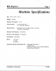
RX-Express Page 1 Machine Specifications Size: 39”1 x 42”h x 15”W Weight: 14 oz. Gearbox Oil Capacity: Vacuum Motor: (1) Three Solution Pump: Diaphragm Type, Continuous 1.25 GPM -45 PSI Max Solution Tank Capacity: Recovery Tank Capacity: Head Speed: 130 Duty, By-Pass 8.5 gallons 8.0 gallons RPMs volts 1/2 HP 8.9 amps Motor: Automatic Stage 5.7” 1 17“ H20 Lift -99 CFM 115 Scrubber CleanMaster Attachment Ciq.
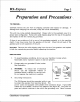
RX=Express Page 2 Preparation and Precautions ~~ TO PREPARE... Carefully remove the unit from its shipping container and inspect damage from shipping has occurred, notify the carrier immediately. for damage. If The unit may come partially disassembled. Please refer to the exploded view for a proper tank configuration. Remove the solid shipping plug from the top of the gearbox and replace it with the vented plug provided.
RX-Express Page 3 the grounding blade to a live terminal. Your terminal is designed to be used on less than 150 volts and has plugs resembling the one shown in Figure A. A grounding adapter is available locally for connecting plugs to 2-prong receptacles. The green (or green and yellow) right lug extending from the adapter must be connected to a properly grounded outlet.
RX-Express Page 4 Operation CONTROLS There are four switches installed in the dash box located on the main handle assembly. Two are for the VACUUM PUMP and CLEANING HEAD. The SOLUTION PUMP has two switches: 1. Automatic, and 2. Manual application of solution. MANEUVERABILITY The ease of handling the RX-Express is a direct result of the rotary extractor head. Its natural cleaning motion provides the “drive” for the The slightest push or pull against the unit.
RX-Express Page 5 I PUMP PRIMING MODE Connect the auxiliary pump line supplied with the unit to the male coupler at the rear of the machine. Disconnect the vacuum hose intake from the left side of the clear dome and place the end of the auxiliary line up into the opening in the dome. Using your hand to create a seal around the line, turn on the vacuum and solution pumps until you see water coming out of the hose.
RX-Express Page 6 Cleaning Instructions 1. Remove the top (recovery) tank and fill the lower (solution) tank with hot water. The higher the temperature of the water, the better the cleaning action of the machine and the chemicals used. However, do not exceed a water temperature of 160°F. When accessible, fill the machine directly from a utility sink using the hose supplied. When this is not an option, a clean, five gallon bucket will suffice.
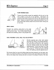
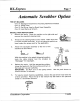
RX-Express Page 7 Automatic Scrubber Option THE KIT INCLUDES One (1) Squeegee Attachment (mounting hardware One (1) Trailer Hook One (1) Pad Driver Head or Brush Head Assembly One (1) Head Removal Wrench INSTALLATION INSTRUCTIONS Remove the tanks. Place the machine 1. remove the standard cleaning head. included) on its right side and 2. Thread on the cleaning head of your choice. Make sure that it mounts counter-clockwise.
“ RX-Express Page 8 PARTS WITH PAD DRIVER PART NO DESCRIPTION 033-039 094-009 143-007 164-001 174-003 016-053 033-099 076-023 052-057 052-288 106-001 Clamp, 1 %” Spring - Wand Holder Nut, %-20 S/S Nylock Screw, %-20 x 1” Eye Bolt Tool, Head Remover Washer, !4” SIS Flat 107-020 154-101 015-144 025-013 033-059 061-100 052-432 061-031 064-020 068-324 131-098 131-099 143-007 143-533 154-001 155-013 177-021 177-022 CleanMaster (079-052) Pad Driver Disk Clamp Jet, H VsVV 8004 s/s - Port RX’s Nipple, 1
RX-Express Page 9 PARTS WITH BRUSH ASSEMBLY (079-050) PART NO DESCRIPTION 033-039 094-009 143-007 143-118 164-001 174-003 016-051 076-023 052-057 052-288 106-001 107-020 154-101 015-144 025-013 033-059 061-100 052-432 061-031 064-020 068-324 131-098 131-099 143-007 143-533 154-001 155-013 177-021 177-022 Clamp, 1 %” Spring, Wand Holder Nut, ?4-20 S/S Nylock Screw, %-20 x 1” Eye Bolt Screw, #8 x %” HXWSHD Tool, Head Remover Washer, %” s/s Flat Brush, Floor Scrub 8004 s/s - Port RX’s Jet, H 1/8VV Nipp
RX-Express Page 10 Maintenance MONTHLY... 1. Check the oil level in the gearbox on a monthly basis. This is a permanent lubricated gearbox. You do not need to change the oil. However, the proper oil level is important. To maintaining check the oil level, remove the vent plug and look Turn the “star” until you can see into the gearbox. the inspection hole in the gear. With the unit sitting flat, the oil level should be up to, but not over, the middle of the gear.
RX-Express threads before Page 11 re-attaching the cleaning head to the machine. WEEKLY... 1. Clean the lid thoroughly by removing 2. Remove and clean the pick-up hose filter inside the solution tank with a vinegar and water solution to remove the chemical deposits. 3. Check the applicator jets in the head to insure a proper solution flow. If the flow is restricted, clean the jets. Twist the jet out. Turn it over. Blow out any obstructions and reinstall the jet.
RX=Express Page 12 Coat themotor shaft with lubricant before reinstalling the cleaning head. Locate the head onto the shaft, making sure the threads are aligned properly, and rotate the head counter-clockwise.
RX-Express Page 13 Repair Guide Make sure the machine IMPORTANT electrical parts. is unplugged before the removal of any Removal of Cleaning Head: 1. First, unscrew the head in the same direction it turns during operation (or clockwise when looking from the underside). 2. Once you have loosened the assembly, spin if off with your hands. If the cleaning head is difficult to remove, you may use a %“ socket wrench on the exposed center nut.
RX-Express 6. 7. Page 14 Remake wire connections with new wire nuts. Re-install in reverse order. Removal of Fiow Control Valve: 1. Disconnect machine from power source. 2. Evacuate all water from unit. 3. Disconnect %” and 3/8” hoses attached to valve. 4. Remove male quick connect from top of frame. 5. Remove %” elbow behind quick connect. 6. Disconnect wires. 7. Lift complete valve assembly from unit. Removal of Cleaning Head / Pivot Frame Assembly: 1. Disconnect machine from power source. 2.
RX-Express Page 15 Machine Parts 22 I 4 ( 21 L ,?i- I 20 19 5 \ .
RX-Express Page 16 62 ‘? ,, ;< \;;: ‘“ ‘“ 63L “=---+”””’’--”” IJ ““”-’ .,x, “ ‘%? Q , ., L . ..>. . J 5 % / 54 \. 48 1.
RX-Express ITEM 1 2 3 4 5 6 7 8a 8b 9 10 11 12 13 14 15 16 17 18 19 20 21 22 23 24 25 26 27 28 29 30 31 32 33 35 36 37 38 39 Page 17 QTY PART NO DESCRIPTION 000-052-099 000-052-276 Insert, #26 Rotary Union %“ NPT Hose, 3/8” Rubber Gearbox, Complete - Spur Base, High Speed Plate, Cast Base - Seal Screw, % -20 x 1” s/s BHCS Star, Stainless Steel Heat Treated Hub, Double Thread RX Vacuum Hose, 1” ID Gray - Vacuum x %“ s/s, HHCS Screw, 5/16 -18 Head, New RX Skid Assembly Nut, % -20 S/S Nylok 000-068-017
‘, RX-Express Page 18 ITEM PART NO DESCRIPTION QTY 40 41 42 43 44 45 46 47 48 49 50 51 52 54 55 56 57 58 59 60 61 62 63 64 65 000-052-117 000-052-050 000-057-055 000-174-011 000-052-090 000-052-071 000-052-085 000-052-061 000-169-119 000-052-104 000-068-018 000-141-025 000-177-018 000-141-026 000-055-056 000-177-019 000-015-141 000-111-129 000-052-117 000-052-448 000-157-115 000-143-167 000-094-034 000-143-051 000-106-033 Insert, #48 Quick Connect, 440 Male w/ Viton - Standard Gasket, Garden Hose W
RX-Express Page 19 11 12 11 ITEM 1 2 3 4 5 7 8 9 10 11 12 13 14 15 PART NO DESCRIPTION QTY 000-159-0361 000-057-060 105-041-001 000-049-0201 000-061-025 000-106-104 000-052-432 000-068-324 000-143-315 000-081-153 000-159-035 000-143-054 000-041-076 000-061-003 Tank, RX-fFxpress Vacuum Gasket, RX-lSxpress Vacuum Cover, Vacuum Tank Assembly Filter Screen, Modified for RX-Expfess Dome Handle, RX-Express Vacuum Tank Bail Stopper Assy, Clear Tank Cuff, 1 %” Gray for Wire Reinforced Vac Hose Hose, 1 %”
RX-Express Page 20 Accessory Parts List PART NO DESCRIPTION 000-068-194 000-068-332 000-079-050 000-079-052 000-163-023 000-164-020 100-011-101 Hose, 1 %” x 15’ Vacuum Hose, 15’ F x F Solution Kit, Auto Scrubber with Brush Assembly Kit, Auto Scrubber with Pad Driver CM-1 Deluxe Upholstery Tool with LP Valve CM-CHSV Upholstery Tool 4“, Closed Head, 1 %” DIA CM S1 1A Carpet Wand 11” LP Powder Coated, 1 %” s/s Rotary Extractor Pad Driver with Hub Rear Assembly, Auto Floor Scrubber Rotary Extractor Brush
RX-Express Page 21 Witing Diagram L M:FmBMcKf ~“’m(”) I GREEN (14) I - ORANGE L CLEANING HEAD (14) BLuE(1S) SOLENOID VALVE 1 SO#J;N VACUUM MOTOR ( “) : 55 WHITE (12) = CleanMaster Corporation 7/21/97
~ RX-Express Page 22 Warranty Repair Policy When requesting warranty information, call or write and provide the following information: 1. 2. 3. 4. When and where the equipment in question Model and serial number of machine. Part number and description of part. Description of failure or defect. Upon receipt of the above information, All packages Authorization After should number. evaluation, a Material was purchased.
RX-Express Page 23 d- tl 5 -3-1 WARRANTY CleanMaster products are warranted to be free of defects either 5 years, 3 years, or 1 year as noted below: * * * * 5 3 1 1 in material for a period of Years on Roto Cast Molded Tanks Years Prorated on Drive Motor Gearbox Assembly (RX-Express Year on Vacuum Motors, Pumps, Switches, Fittings, Etc.